

Standart Uzatılabilir Römork Boyutları Referans Matrisi
Aşırı uzun yükleri doğru Uzatılabilir Römork Boyutlarına uyarlamak hassas boyutsal planlama gerektirir. Şasi uzunluğunu uzatırken, yük operatörleri güverte açıklığını, köprü yasası aks aralığını ve eğilme momentlerini dengelemelidir. Teleskopik şasimizi, tüm uzatma aşamalarında yüksek torsiyon direncini koruyacak şekilde tasarlıyoruz ve boş ağırlığı optimize ediyoruz.
Aşağıda, ağır yük römorku türleri arasında standart kapalı ayak izlerini ve maksimum operasyonel uzatmaları karşılaştıran temel mühendislik referans matrisi yer almaktadır.
Mühendislik Boyutlandırma Matrisi: Boyutlar, Açıklıklar ve Kapasiteler
| Treyler Yapılandırması | Geri Çekiliş Uzunluğu | Maksimum Uzatılmış Uzunluk | Kullanılabilir Güverte Genişliği | Yüklenmiş Güverte Yüksekliği | Aks Konfigürasyonları | Derecelendirilmiş Yük Kapasitesi |
|---|---|---|---|---|---|---|
| Uzatılabilir Düz Yatak (Tek Aşamalı) | 48 ft / 14,63 m | 80 ft / 24,38 m | 102 in / 2.590 mm | 59 in / 1.500 mm | 2 ila 3 Aks | 88.000 lbs / 40 ton |
| Genişletilebilir Düz Yatak (Çift Aşamalı) | 53 ft / 16.15 m | 120 ft / 36.58 m | 102 in / 2.590 mm | 59 in / 1.500 mm | 3 ila 4 Aks | 50.000 kg / 50 ton |
| Genişletilebilir Basamak Güverte | 48 ft / 14,63 m | 75 ft / 22.86 m | 102 in / 2.590 mm | 36 in / 915 mm | 2 ila 4 Aks | 43.000 kg / 43 ton |
| Genişletilebilir Düşük Yatak (RGN Çukur) | 26 ft / 7.92 m (Çukur) | 50 ft / 15.24 m (Çukur) | 262–305 cm / 2.590–3.048 mm | 457–610 mm / 18–24 in | 3 ila 3+2 Aks | 60.000 kg / 60 ton |
| Çok Aşamalı Teleskopik Bıçak Römorku | 65 ft / 19.81 m | 230+ ft / 70.10 m | 100–118 in / 2.540–3.000 mm | 38–48 in / 965–1.220 mm | 3 ila 6 Aks (Yönlendirilmiş) | 120.000 lbs / 55 ton |
Çekirdek Boyutsal Kriterler
- Kapalı vs. Uzatılmış Uzunluk: Standart şasi yasal otoyol uzunluklarında başlar (48 ft veya 53 ft) ve kalibre edilmiş 2 ft ile 5 ft (600 mm ile 1.500 mm) aralıklı iç kaydırma kirişleriyle uzatılır.
- Güverte Yükseklik Profilleri: Uzatılabilir düşük platformlar, yüksek sanayi bileşenlerini üst yapıların altına sığdırmak için 18 inç (457 mm) seviyesine kadar ultra düşük yükleme platform yüksekliği sağlar, uzatma basamaklı platformlar ise uzun, orta yükseklikte makineler için ortalama 36 inç (915 mm) yüksekliktedir.
- Aks Konfigürasyonu ve Yükleme Mekanikleri: Tekerlek izi genişledikçe, ortadaki açıklıkta yoğun yük kapasitesi azalır. Köprü formülü uyumluluğunu korumak ve sık dönüşlerde lastik sürtünmesini azaltmak için 80 ft (24.38 m) ötesine uzanan platformlarda hidrolik kendi kendine takip eden veya zorunlu yönlendirmeli aks hatları kullanıyoruz.
Genişletilebilir Düz Yataklı Römork Ölçüleri (Trombon Römorklar)
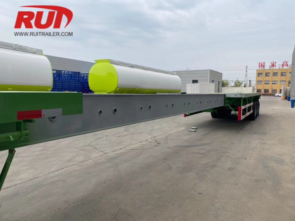
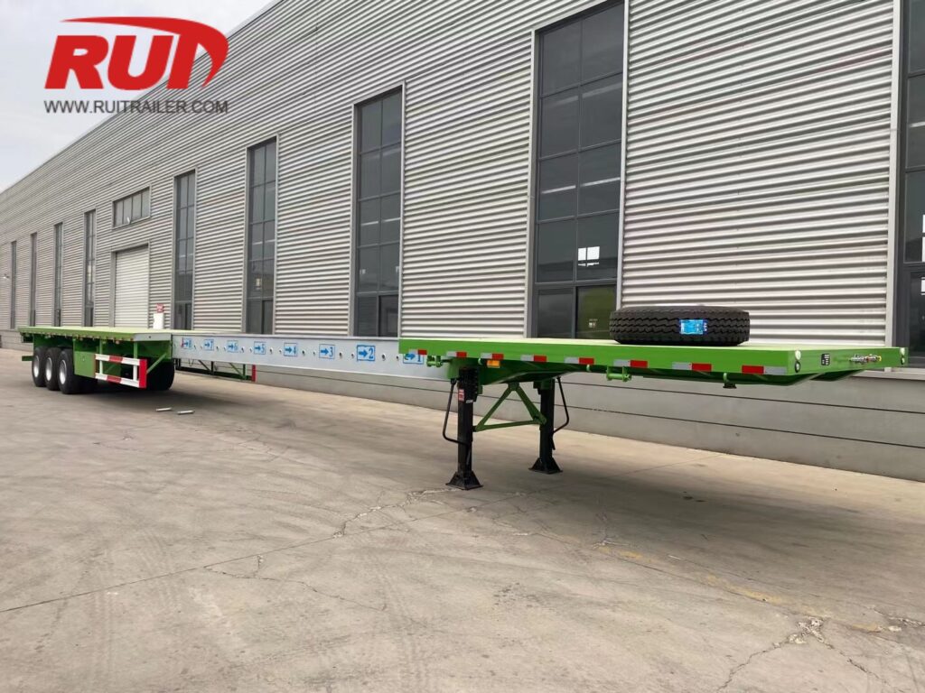
Trombon ve uzatılmış düz yataklı römorklarımızı, yapısal çelik kirişler, uzun borular, donatı demetleri ve kendi kendine destekli uzun yükleri taşımak için tasarlıyoruz, aynı zamanda standart yasal boyutlar altında boş çalışabilecek kadar çevik kalıyoruz.
Standart Geri Çekilmiş Şasi Boyutları
Kapanınca, uzatılmış düz yataklarımız, ölü yük dönüşümlerinde izin almadan kullanılabilen standart otoyol konfigürasyonlarına uygun hale gelir:
Temel 48 ft Model: 48 ft (14.63 m) geri çekilmiş uzunluk ve 102 inç (2.59 m) standart güverte genişliği ile.
Temel 53 ft Model: 53 ft (16.15 m) geri çekilmiş uzunluk ve 102 inç (2.59 m) standart güverte genişliği ile.
Kullanılabilir Güverte Genişliği: 8 ft 6 inç (2.59 m), yan kazık cepleri, sürtünme rayları ve entegre boru cepleri ile.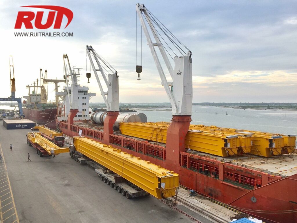
Tek Kademe ve Çift Kademe Uzatma Aralıkları
Aşırı uzunluklara uyum sağlamak için, aşınma pedleri boyunca düzgün kayar yüksek mukavemetli çelik teleskopik kutu kirişler kullanıyoruz:
Tek Kademe Teleskopik Uzantılar: 48 ft'lik bir römorku 80 ft'ye (24.38 m) veya 53 ft'lik bir römorku 90 ft'ye (27.43 m) kadar uzatır.
Çift Kademe Teleskopik Uzantılar: Çift kaydırmalı merkezi kutu kiriş sistemi kullanır ve şasiyi toplamda 53 ft'den 120 ft'ye (36.58 m) kadar uzatır.
Farklı uzun yük taşımaları için operasyonel parametreleri gözden geçirmek üzere, uzatılabilir römork çok yönlü yük kapasitesi kılavuzumuza bakın Çerçeve derecelendirmelerini farklı aralıklar boyunca değerlendirmek.
| Ölçüt | 48 ft Tek Kademe | 53 ft Tek Kademe | 53 ft Çift Kademe |
|---|---|---|---|
| Kapalı Uzunluk | 48 ft (14.63 m) | 53 ft (16.15 m) | 53 ft (16.15 m) |
| Maksimum Uzatılmış Uzunluk | 80 ft (24.38 m) | 90 ft (27.43 m) | 120 ft (36.58 m) |
| Güverte Genişliği | 102 in (2.59 m) | 102 in (2.59 m) | 102 in (2.59 m) |
| Yüklenmiş Güverte Yüksekliği | 59 in (1.498 mm) | 60 in (1.524 mm) | 61 in (1.549 mm) |
| Pin Kilitleme Aralıkları | 2 ft / 5 ft (0.6 m / 1.5 m) | 2 ft / 5 ft (0.6 m / 1.5 m) | 2 ft / 5 ft (0.6 m / 1.5 m) |
22.5 İnç Lastiklerde Üst Güverte Yükseklik Profilleri
Standart 295/75R22.5 veya 11R22.5 ağır hizmet radial lastiklerde çalışırken, uzatılabilir düz yatak güverte yüksekliklerimiz doğrudan forklift ve vinç yüklemesi için optimize edilmiştir:
Boş Yüksek Güverte Yüksekliği: Arka süspansiyonda 61 inç ile 63 inç (1.549 mm ile 1.600 mm) arasında.
Yüklü Yüzey Yüksekliği: Standart yasal aks yüklemeleri altında 59 inç ile 60 inç (1.498 mm ile 1.524 mm) arasında oturur.
Alt Çerçeve Boşluğu: Orta açıklıkta teleskopik merkez kirişinin altında 14 inç ile 18 inç (355 mm ile 457 mm).
Havalı Kilitli Çivi Aralıkları ve Konumlandırma
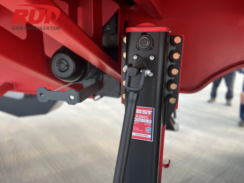
Teleskopik şasi sistemlerimiz, sürücü tarafı valf konsolundan veya kabin içi havalı anahtarlar aracılığıyla kontrol edilen ağır hizmet tipi havalı kilitli çiviler içerir:
Kilit Aralıkları: Ana yapısal kutu kiriş boyunca her 24 inç (610 mm) veya 60 inç (1.524 mm) aralıklarla konumlandırılmış hassas delikli çivi durdurucuları.
Enerji Zinciri Kablo Rayları: Tam kapalı e-zincirler, şasi açılıp kapandıkça hava fren hatlarını ve elektrik bağlantılarını sıkışma, takılma veya gerilme riskinden korur.
Hava Tahrikli Serbest Bırakma: Yaylı güvenlik kilitleri, taşıma sırasında hava basıncı kaybı olsa bile çivilerin mekanik olarak kilitli kalmasını sağlar.
Genişletilebilir Basamaklı Güverte ve Düşük Güverte Boyutlandırması
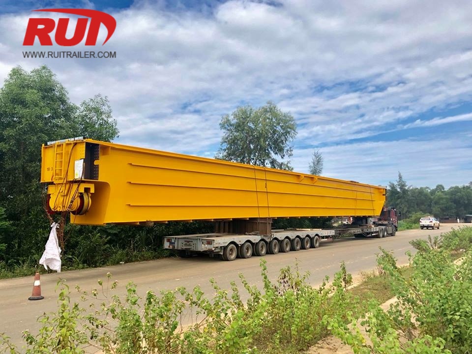
Genişletilebilir basamaklı (düşük güverte) römorklarımız, standart düz yataktan çok yüksek olan uzun yükleri taşımada karşılaşılan zorluğu çözer. Ağırlık merkezini alçaltarak ve değişken güverte uzunlukları sağlayarak, bu römorklar yüksek, kendi kendine destek sağlayan endüstriyel yükleri taşımayı mümkün kılar ve standart köprü açıklık sınırları içinde kalmanızı sağlar.
Üst Güverte Uzunluğu ve Genişletilebilir Alt Güverte Boyutları
Şasi düzeni, kullanılabilir güverte alanını sabit üst güverte ve teleskopik alt güverte olarak ayırır:
- Üst Güverte (Gooseneck Alanı): Genellikle 10 ft ile 11 ft (3.048 mm ile 3.353 mm) uzunluğunda olup, yükleme desteği ekipmanları, donanım veya daha küçük ikincil yükler için standart 60 inç (1.524 mm) yüklü güverte yüksekliği sağlar.
- Kapalı Alt Güverte: Temel temiz güverte uzunluğu 37 ft ile 42 ft (11.278 mm ile 12.800 mm) arasında sunar.
- Genişletilmiş Alt Güverte: Tek aşamalı teleskopik merkez kirişler, ana güverteyi 63 ft–75 ft (19.200 mm ile 22.860 mm) arasında genişletir ve toplam genişletilmiş römork uzunluğunu 86 ft (26.212 mm) kadar çıkarır.
+------------------+----------------------------------------------------+
| Sabit Üst Güverte | Genişletilebilir Alt Güverte (Ana Güverte) |
| 10 ft - 11 ft | Kapalı: 37 ft - 42 ft ===> Genişletilmiş: 75 ft'ye kadar |
+------------------+----------------------------------------------------+
Yüksek Yükseklikli Yükler İçin Düşük Profil Güverte Yükseklikleri
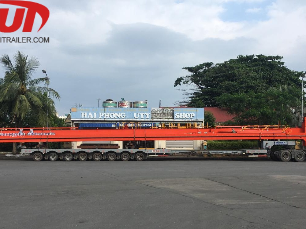
Alt güverte yüksekliği, yüksek makineler, gemiler ve yapısal bileşenler için yasal üst açıklık sağlar. Standart genişletilebilir düşürme güverte römorku özelliklerimiz, yüklü alt güverte yüksekliğini arasında sağlar 34 inç ve 40 inç (864 mm ile 1.016 mm) 255/70R22.5 düşük profil lastiklerde.
Aşırı dikey açıklık gerektiğinde, 17.5 inçlik çalışma takımı kullanarak yüklenmiş güverte yüksekliğini 30 inç ile 33 inç (762 mm ile 838 mm) arasına düşüren süper düşük konfigürasyonlar tasarlarız. Daha düşük yer profilleri gerektiren aşırı uygulamalar için, ayrıca özel ekipmanlar da üretmekteyiz, örneğin düşük profil güverte modüler römork sıkı üst açıklık sınırlamaları için tasarlanmıştır.
Genişletilebilir Düşük Güverte Boyutsal Özellikleri
| Özellik Metrik | Standart İmparatorluk | Standart Metrik |
|---|---|---|
| Toplam Uzunluk (Kapalı) | 48 ft / 53 ft | 14.630 mm / 16.154 mm |
| Toplam Uzunluk (Tam Genişletilmiş) | 75 ft ile 86 ft | 22.860 mm ile 26.212 mm |
| Ana Kuyu Uzunluğu (Genişletilmiş) | 75 ft'ye kadar | 22.860 mm'ye kadar |
| Yüklenmiş Kuyu Yüksekliği | 34 in ile 40 in | 864 mm ile 1.016 mm |
| Standart Güverte Genişliği | 8 ft 6 in (102 in) | 2.590 mm |
| Çıkıntı Uzatmalı Genişlik | En fazla 10 ft 6 in | En fazla 3.200 mm |
| Zemin Yükseklikten Temizleme (Yüklü) | 8 in ile 10 in arasında | 203 mm ile 254 mm arasında |
Gooseneck Düşüş Geçişi ve Akışkan-Kuyruk Boşlukları
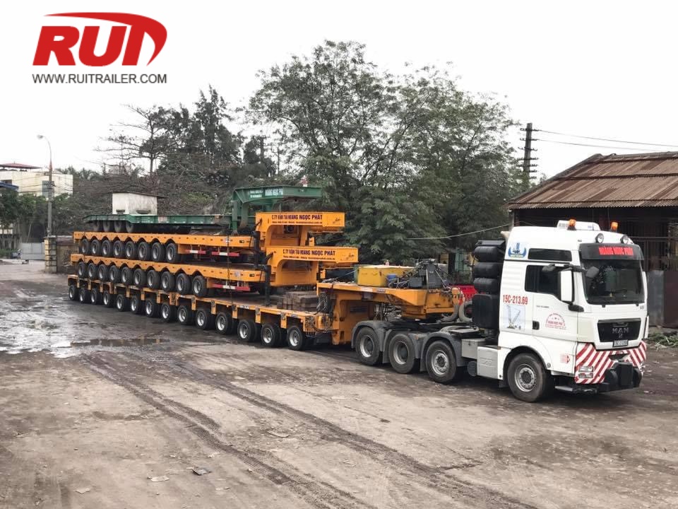
- Düşüş Geçişi Eğimi: Üst güverteden alt güverteye temiz 45 derece veya 90 derece geçiş ile inşa edilmiştir. Bu tasarım, transit sırasında yüksek yapısal yüklerin uzun mesafe boyunca yüksek merkezlenmesini önler.
- Arka Körük Geçişi: Arka çalışma takımına konik geçiş, uzun ekipmanların kuyuyu temizlemesini sağlar ve arka aks çerçevesine takılmasını engeller.
- Akışkan-Kuyruk ve Rampa Seçenekleri: İsteğe bağlı 4 ft ile 5 ft (1.219 mm ile 1.524 mm) arka akışkan-kuyruklar ve ağır hizmet tipi yaylı veya hidrolik rampalar, sürme ekipmanları için 14 ila 16 derece yükleme açısı sağlar.
Uzatılabilir Lowboy ve RGN Römork Boyutları
Endüstriyel otoklavlar, rafineri bileşenleri veya ağır makineler gibi yüksek, kendi kendine destekleyen yükleri taşırken, düşük zemin yüksekliği ile ayarlanabilir uzunluğun birleşimi çok önemlidir. Uzatılabilir düşük taban ve çıkarılabilir boğaz platformlarımız, dikey açıklıkları zorlayan durumlarda uzun dingil mesafelerine uyum sağlar. Standart platform düzenlerini keşfetmek için kapsamlı lowboy römork kılavuzumuza bakın; türler, özellikler ve kullanımlar.
26 ft Kapalı'dan 65 ft Uzatılmış'a kadar net yükleme alanı
Net yükleme alanı, yoğun ağır yükler için ana platformu sağlar. Bizim uzatılabilir lowboy boyutlarımız aşağıdaki standart uzunluk aşamalarını sağlar:
- Geri Çekilmiş Temel Kuyu: Standart bölgesel seyahat ve boş dönüşler için 26 ft ile 30 ft (7.92 m ile 9.14 m).
- Tam Uzatılmış Alan: Uzun açıklıklı yapılar için 50 ft ile 65 ft (15.24 m ile 19.81 m) net yükleme alanı.
- Toplam Genel Uzunluk: 53 ft (16.15 m) kapalıdan 90+ ft (27.43+ m)ye kadar uzanır, boğaz ve arka tandem/tridem makara montajlarını içerir.
Ultra-Düşük Yükleme Zemini Yükseklik Profilleri (18 inç ile 24 inç)
Zemin yüksekliğini minimize etmek, otoyol köprüleri ve elektrik hatları altında ekstra alan sağlar:
- Yüklü Yüzey Yüksekliği: Tam yük altında 18 inç ile 24 inç (457 mm ile 610 mm).
- Yüklenmiş Zemin Yüksekliği: 4 inç ile 6 inç (102 mm ile 152 mm) çalışma boşluğu, demiryolu geçitleri ve düzensiz kavşaklar boyunca altına çökmesini önlemek amacıyla tasarlanmıştır.
- Güverte Tasarımı Varyantları: Düz kuyu, düşey yan kiriş veya kiriş ve demet yapılandırmaları, ultra yüksek yük taşıma için.
Ana Kiriş Kaydırma Takviyeleri ve Hidrolik Menteşe Kilitleri
Ağır yükler altında teleskopik hareketler, sağlam yapısal kilitleme mekanizmaları gerektirir. Bu germe kuyularını yüksek mukavemetli teleskopik yapısal kutu kirişler ve hassas kilitleme sistemleri ile inşa ediyoruz:
| Boyutsal Parametre | İmparatorluk Ölçüsü | Metrik Ölçü |
|---|---|---|
| Geri Çekilmiş Kuyu Uzunluğu | 26 ft – 30 ft | 7.92 m – 9.14 m |
| Maksimum Uzatılmış Kuyu Uzunluğu | 50 ft – 65 ft | 15.24 m – 19.81 m |
| Yüklenmiş Güverte Yüksekliği | 18 inç – 24 inç | 457 mm – 610 mm |
| Zemin Boşluğu (Yüklenmiş) | 4 inç – 6 inç | 102 mm – 152 mm |
| Kilitleme Çubuğu Aralıkları | Her 24 inç ile 60 inç arasında | Her 600 mm ile 1.500 mm arasında |
- Yüksek Verimli İç ve Dış Kirişler: Uzun açıklıklar boyunca eğilmeye direnç göstermek için ağır mukavemetli çelikten imal edilmiştir, ölü ağırlık eklemeden.
- Hava ve Hidrolik Çubuk Durdurucuları: Yüksek kesme mukavemetli kilit çubukları, uzatma omurgası boyunca belirli aralıklarla güvenli bir şekilde kilitlenir.
- Düz ve Çıkarılabilir Geçişler: Operasyonel esneklik sağlayan ön boyun tasarımlarımızla sorunsuz bağlantı, RGN çıkarılabilir boğaz römork serimizde bulunur.
Çok Aşamalı Teleskopik Bıçak Römork Boyutları
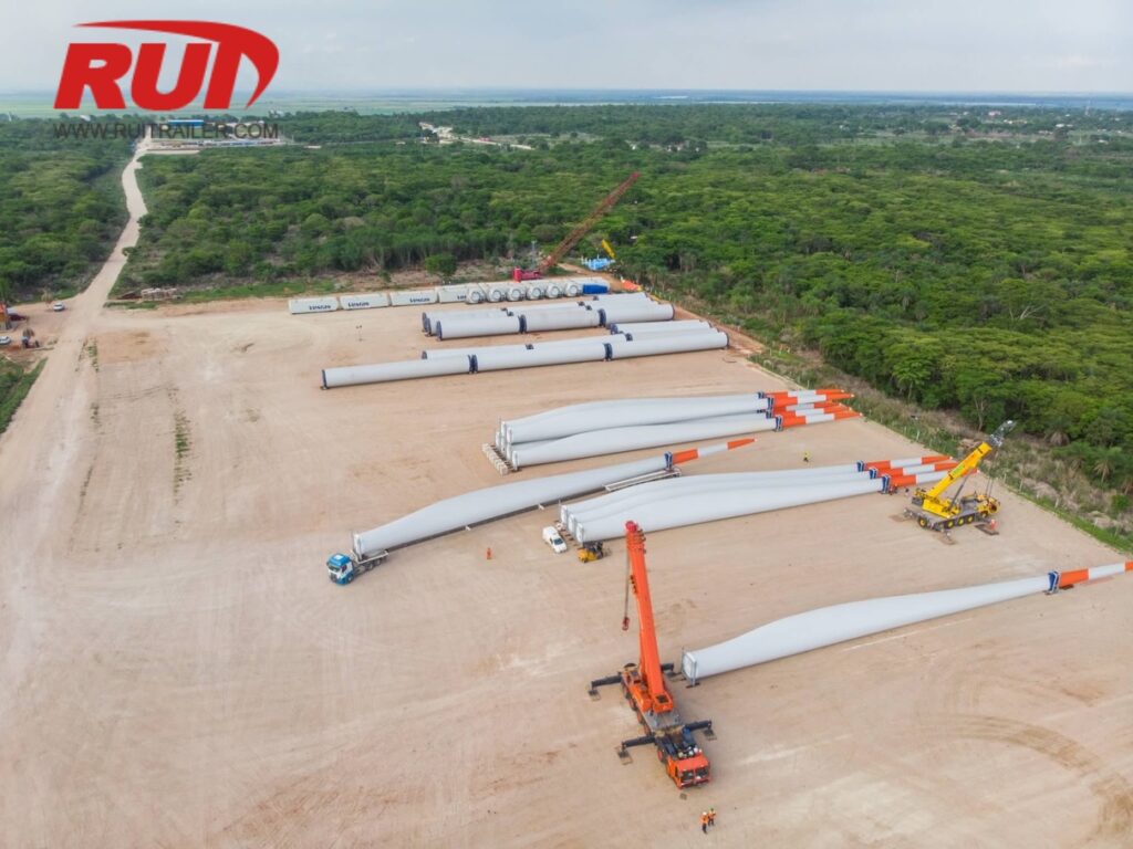
Modern kıyı rüzgar türbini kanatlarının taşınması aşırı erişim ve torsiyonel stabilite gerektirir. Çok aşamalı teleskopik kanat römorklarımızı, boş dönüşlerde sıkı yol uyumu sağlarken büyük kanat uzunluklarını karşılamak üzere tasarlıyoruz.
Çok Aşamalı Teleskopik Uzatma Dinamikleri
Çok aşamalı teleskopik römork şaselerimiz, kanat uzunluğuna göre dinamik olarak ayarlanan 3 aşamalı, 4 aşamalı ve 5 aşamalı uzatma kirişleri kullanır:
- Kapanış Uzunluğu: Yasal boş transit için 19,8 m ile 21,9 m (65 ft ile 72 ft) arasında.
- Maksimum Uzatılmış Uzunluk: Sorunsuzca 53,3 m’den 70 metreyi aşan 230+ ft’ye kadar genişler.
- Ara Kilitleme Adımları: Otomatik pnömatik kilit pinleri, teleskopik bölümleri her 0,9 m ile 1,5 m (3 ft ile 5 ft) arasında özel aralıklarla güvence altına alır.
- Arka Bogie Konfigürasyonu: 3 ila 6 hidrolik sarkmalı aks hattı, sık dönüş yarıçapı ve otomatik izleme direksiyon sağlar.
Bölgesel güzergah konfigürasyonları için, özel bir rüzgar türbini kanat treyleri kullandığınızda, toplam kombinasyon uzunluğunuz izin verilen şerit yolları içinde kalırken yol daralma noktalarını aşar.
Torsiyonel Kutu-Kiriş Profili
Aşırı uzatma açıklıkları ciddi eğilme momentleri üretir. Merkezi omurgayı, yüksek mukavemetli, kapalı kutu-kiriş profili kullanarak inşa ediyoruz; bu profil yüksek verimli yapı çeliğinden üretilmiştir:
- Şasi Direnci: Kapalı merkezi omurga, yan eğilmeyi engeller ve 200 ft (61 m) üzerindeki açıklıklar boyunca torsiyonel şasi bükülmesini ortadan kaldırır.
- İç Kablo/Hortum Yolları: Enerji zincirleri, teleskopik kirişler içinde içten çalışır, hidrolik hatları ve elektrik kablolarını bağlanma veya yol kalıntılarından korur.
| Özellik Parametresi | Standart İmparatorluk | Standart Metrik |
|---|---|---|
| Geri Çekilmiş Toplam Uzunluk | 65 ft 7 in | 20.000 mm |
| Tam Genişletilmiş Toplam Uzunluk | 232 ft 11 in | 71.000 mm |
| Genişletme Aşamaları | 3 ila 5 Aşamalı Teleskopik | 3 ila 5 Aşamalı Teleskopik |
| Yüklenmiş Güverte Yüksekliği (Arka Körük) | 37 in ila 41 in | 950 mm ila 1.050 mm |
| Şasi Genişliği | 8 ft 4 in ila 9 ft 10 in | 2.550 mm ila 3.000 mm |
Hidrolik Döner Tabla ve Bıçak Kök Adaptör Boyutlandırması
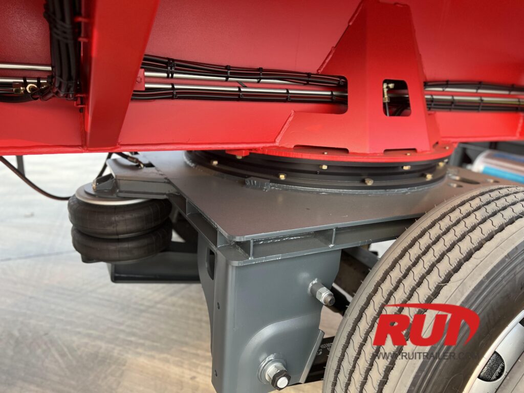
Bağlama kök uç çaplarının sert montaj arayüzleri gerektirir, bu arayüzler ivmelenme ve frenleme kuvvetlerini emebilir:
- Entegre Döner Tablalar: Hidrolik kaydırmalı destekler taşıma sürtünmesini emer ve düzensiz arazi üzerinde bıçak eğilimini telafi eder.
- Kök Sıkıştırma Bağlantı Elemanları: Evrensel cıvata-daire kök adaptörleri, standart 3,0 m ile 4,5 m (9,8 ft ile 14,8 ft) bıçak kökü çaplarına uyacak şekilde ayarlanabilir.
- Aşırı Arazi Hareket Kabiliyeti: Dağlık rüzgar çiftliği erişim yolları için, şasiyi özel bir ekipmanla eşleştirerek rotor kanat adaptörü ağaç hatlarını ve dar yamaç virajlarını temizlemek için 60 dereceye kadar bıçak eğimi ve tam 360 derece döndürme imkanı sağlar.
Genişlik, Temizlik ve Yapısal Eğilme Parametreleri
Ağır nakliye ekipmanlarının yapılandırılmasında toplam genişliği, traktör temizliği ve orta açıklık şasi eğilmesini kontrol etmek esastır. Uzatılabilir römork boyutları uzadıkça, yapısal geometrinin yönetimi, aracın yasal uyumlu, stabil ve maksimum yük altında yol yüzeyinden uzak kalmasını sağlar.
Şasi Genişliği Derecelendirmeleri ve Döner Destekler
Standart uzatılabilir platformlar, izin verilmeyen karayolu geçiş kurallarına uygun olmak için 2,59 m (8 ft 6 in) temel taşıma genişliğine sahiptir. Büyük yükler, ağır ekipmanlar ve geniş makineler için, çevre kirişleri boyunca ağır hizmet tipi döner destekler (yan braketler) entegre edilir.
- Standart Temel Genişlik: 2,59 m (8 ft 6 in)
- Genişletilmiş Destek Genişliği: 10 ft 0 in ile 12 ft 0 in (3,05 m ile 3,66 m / 3.050 mm ile 3.660 mm)
- Çıkıntı Kapasitesi: Ağır ahşap veya alüminyum çıkıntı tahtaları kullanarak dağıtılmış çevre yüklerini desteklemek için derecelendirilmiştir.
| Özellik Parametresi | Standart İmparatorluk | Metrik (ISO) | Uygulama / Fonksiyon |
|---|---|---|---|
| Taban Güverte Genişliği | 8 ft 6 in (102 in) | 2.590 mm | Yasal seyahat şeridi genişliği standardı |
| Çıkıntı Uzatmalı Genişlik | 10 ft 0 in – 12 ft 0 in | 3.050 mm – 3.660 mm | Geniş makine ve gemi desteği |
| Gusset Salınım Yarıçapı | 84 in – 110 in | 2.134 mm – 2.794 mm | Çok akslı traktörler için kabin ve çerçeve açıklığı |
| Kingpin Geri Dönüş Ayarları | 16 in, 24 in, 36 in | 406 mm, 610 mm, 914 mm | Traktör sürüş aksı ağırlık dağılımını optimize eder |
| Omurga Ön Eğrilik Kemer | 1.5 in – 3.5 in | 38 mm – 89 mm | Yük altında açıklık ölçüsüne karşı önlem |
Gooseneck Salınım Yarıçapı, Kingpin Ayarları ve Traktör Temizliği
Sıkışık manevralar sırasında traktör şasisi, kabin uyku alanı ve römork boynu arasında uygun açıklık, temasın önüne geçer. Farklı traktör tekerlek izleri ve arka tahrik aksı gruplarına uyum sağlamak için ayarlanabilir, çok pozisyonlu ticari kingpinler (2 inç / 50,8 mm ve 3,5 inç / 88,9 mm seçenekleri) tasarlıyoruz.
- Çift Kingpin Konumları: Çift ayar baz plakaları, 16 inç (406 mm) ile 36 inç (914 mm) geri çekilmeler arasında hızlı ayarlamalara olanak tanır.
- Gooseneck Boşluğu: 84 inç ile 110 inç (2.134 mm ile 2.794 mm) arasında tasarlanmış salınım profilleri, 3 akslı ve 4 akslı ağır yük traktörlerine uyum sağlar ve yapılandırmalarla sorunsuz entegre olur, örneğin katlanabilir gooseneck düşük yükleyici arka vinç çerçevesi ve çamurluklar ile teması önlemek için.
Orta açıklıkta çökmeyi önlemek için Önceden Kavisli Omurga Mühendisliği
Bir teleskopik kiriş uzun açıklıklara uzandığında, doğal eğilme momentleri artar. Uygun tasarım olmadan, bu esneme, römorkun ortasında yapısal çöküntüye neden olur, yüklü güverte yerden yüksekliği güvenli sınırların altına düşer ve demiryolu geçitleri ile yol tepeciklerinde yerle temas riski artar.
- Yerleşik Yukarı Kavis: Ana merkezi omurumuzu pozitif önceden kavisli (boşken 1.5 inç ile 3.5 inç / 38 mm ile 89 mm yukarı kavisli) olarak imal ediyoruz.
- Yük altında açıklık kontrolü: Römork maksimum uzatma ile yoğun yük taşıdığında, tasarlanmış esneklik, güverteyi düz ve seviyeli bir düzleme çeker.
- Yüksek Verimli Çelik Yapı: Yüksek mukavemetli çelik kutu kirişler kullanılarak inşa edilen şasi, kalıcı deformasyona direnç gösterir ve çeşitli uzama uzunluklarında tam yapısal bütünlüğü korur.
Aks Aralığı, Direksiyon Geometrisi ve Köprü Kanunu Uyumu
Genişletirken uzatılabilir römork boyutları aşırı yükler için, ağırlık dağılımını ve manevra kabiliyetini yönetmek kritik hale gelir. Dingil tabanını uzatmak, Federal Köprü Formülü kapsamında dingil yüklemelerini değiştirir ve yol üzerinde yasal ve manevra kabiliyetli kalmak için belirli dingil grubu yayılımı ve aktif direksiyon mekanizmaları gerektirir.
Köprü Formülü Dingil Gruplama Konfigürasyonları
Şasi uzatmak, iç köprü aralığını kaydırır ve karayolu ağları genelinde yasal dingil ağırlık izinlerini değiştirir. Arka akslarımızı çok yönlü aralık düzenleriyle tasarlıyoruz:
Standart İkili ve Üçlü Yayılım: Toplam araç ağırlık sınırlarını (GVWR) optimize etmek için 54 inç (1.370 mm), 60 inç (1.524 mm) veya 72 inç (1.829 mm) olarak ayarlanmış sabit veya kaydırılabilir dingil aralıkları.
Geniş Yayılım ve Dörtlü Konfigürasyonlar: 108 inç (2.743 mm) veya modüler 4-dingil gruplarıyla yoğun ağırlığı yol köprüleri üzerinde eşit şekilde dağıtmak için aralıklar.
Boş Ağırlık Optimizasyonu: Kesin kingpin-orta dingil mesafe ayarları, bölgesel köprü formüllerine uyumu sağlar ve traktör sürüş akslarını aşırı yüklemeden korur.
+------------------------------------------------------------------------------------+
| Geri Çekilmiş / Uzatılmış Dingil Tabanı | Köprü Formülü Uyumu | Dingil Grubu Yük Dağılımı |
+------------------------------------------------------------------------------------+
| 48 ft (14.6 m) kapalı | Standart Yasal Sınırlar | Doğrudan 50/50 Tandem |
| 80-120+ ft (24.4-36.5+ m) açık | İzin verilen Aşırı Boyutlu Köprü | Aktif Dağıtılmış |
+------------------------------------------------------------------------------------+
Hidrolik Zorunlu Direksiyon Sistemleri (55° Açısına Kadar)
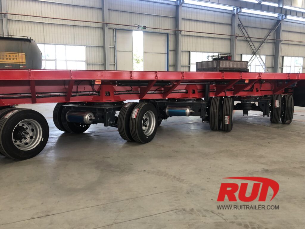
Uzun uzatma römork boyutları, kentsel veya dağlık rotalarda ciddi lastik sürtünmesi ve dar dönüş zorlukları yaratır. Çok aşamalı ve ağır yük römorklarımızı yüksek açıdaki direksiyon entegrasyonu ile donatıyoruz:
Küpeşte ve Döner Tabla Kontrolü: Mekanik-hidrolik direksiyon bağlantıları, boğazlı kral pim pivot açısını arka aks makasıyla senkronize eder.
Aşırı Dönüş Yarıçapı: Hidrolik akslar, ağır sanayi uygulamaları için 55 dereceye kadar kademeli direksiyon açıları sağlar, kesme izleme işlemini önemli ölçüde azaltır.
Kablosuz Uzaktan Kontrol: El tipi kablosuz uzaktan kumanda, operatörlerin karmaşık kavşaklar ve dar şantiye alanlarında arka aksleri bağımsız olarak yönlendirmesine olanak tanır.
Boş dönüşlerde kaldırma aksı kullanımı
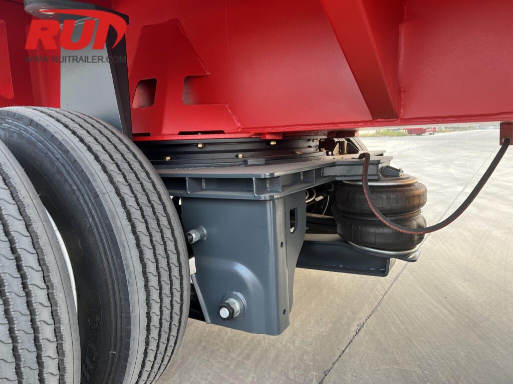
Yük taşımayan dönüşlerde çok akslı montajların sürüklenmesi yakıt tüketimini ve lastik aşınmasını artırır.
Otomatik Pnömatik ve Hidrolik Kaldırma Sistemleri: Boşta iken ön veya arka yardımcı aksları kaldırarak yer temaslı tekerlek tabancasını kısaltın.
Lastik Sürtünmesi ve Sürüklenme Azaltma: Boşken dar dönüşlerde yan lastik sürtünmesini ortadan kaldırır, lastik ömrünü uzatır ve ulaşım rotalarında ücret kategorisi ücretlerini düşürür.
Yük Boyutlandırma ve Yükleme Ölçüleri Uyumlaştırması
Yükünüzün fiziksel alanını doğru uzatılabilir römork boyutlarıyla eşleştirmek, yapısal aşırı yüklenmeyi, aşırı eğilmeyi ve üst açıklık ihlallerini önler. Telescopic şasi tasarımımızı üç farklı yük kategorisi etrafında mühendislik yapıyoruz:
Hazır Döşemeli Beton ve Yapısal Çelik Kirişler
Uzun yapısal açıklıklar genellikle kendi kendine destek sağlar, ancak belirlenmiş yatak noktalarında hassas destek yerleştirmesi gerektirir:
Destek Noktası Yerleştirme: Teleskopik şasi kilitlenme aralıklarımızı, kirişin mühendislik seçili noktalarının doğrudan altına hizalayacak şekilde yapılandırıyoruz, böylece taşıma sırasında olumsuz eğilme momentlerini önlüyoruz.
Açıklık ve Yükleme Kapasitesi: Standart 53 ft (16.15 m) uzunluğundaki düz yataklı taşıma aracı, 90 ft (27.43 m) uzatıldığında yapısal yükü merkezi omurgaya kaydırır. Kendinden destekli olmayan çelik elemanlar için, yasal eğilme sınırlarını 1.5 inç (38 mm) altında tutmak amacıyla orta açıklık blokajı veya çift omurga şasi tasarımları gereklidir.
Rüzgar Türbini Kuleleri ve Rotor Kanatları
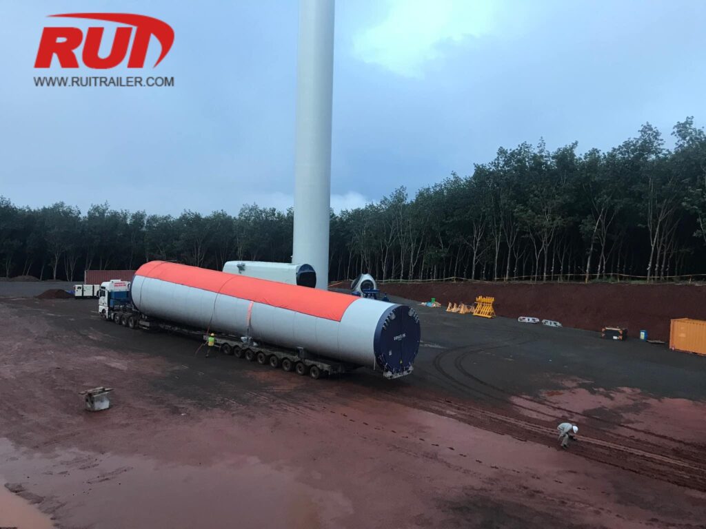
Rüzgar enerjisi bileşenleri tamamen farklı boyutsal zorluklar sunar:
Kule Bölümleri: Büyük çaplı taban ve orta bölümler, maksimum yoğunlaştırılmış ağırlık kapasitesi ile birlikte, otoyol üst geçitlerini aşmak için ultra-düşük yüklü güverte yüksekliği (18 inç / 457 mm altında) gerektirir. Ağır yükler için ağır hizmet tipi ön yüklü düşük yataklı treylerimizi kullanıyoruz bu ağır silindirik yükleri güvenli bir şekilde taşımak için uzatılabilir iyi güverte konfigürasyonlarıyla.
Rotor Kanatları: Modern 70 m ile 100+ m (230 ft ile 330 ft) kanatlar minimum aks ağırlığı uygular, ancak büyük kuyruk salınımı ve rüzgar kayması üretir. 3 aşamalı ve 4 aşamalı teleskopik kanat treylerleri inşa ediyoruz, 240 ft (73.15 m)ye kadar uzatılabilir, döner tabla kök adaptörleri ve zorunlu yönlendirmeli arka dingillerle, dar dönüşlerde güvenli takip sağlar.
Basınçlı Kaplar İçin Tavan Yükseklik Ölçümü
Endüstriyel kaplar, fraksiyonatörler ve otoklavlar katı dikey boyut yönetimi gerektirir:
Transit Yükseklik Hesaplaması: Toplam transit yüksekliği, kapların dış çapı ile taşıma sehpası yüksekliği ve yüklü güverte yerden yüksekliği toplamıdır.
Güverte Optimizasyonu: Standart 14 ft 6 inç (4.42 m) yüksekliğindeki köprü geçişi altında 12 ft (3.66 m) çapında bir tank taşımak için, yüklü güverte yüksekliği 24 inç (610 mm) aşmamalıdır. Bu aşırı yükler için, tam yük altında 12 inç ile 15 inç (305 mm ile 381 mm) arasında yere yakın olacak şekilde ayarlanabilen düşük profilli uzatılabilir iyi güverte konfigürasyonları kullanıyoruz.
Özel Teleskopik Römork Mühendisliği ve Üretim Yetenekleri
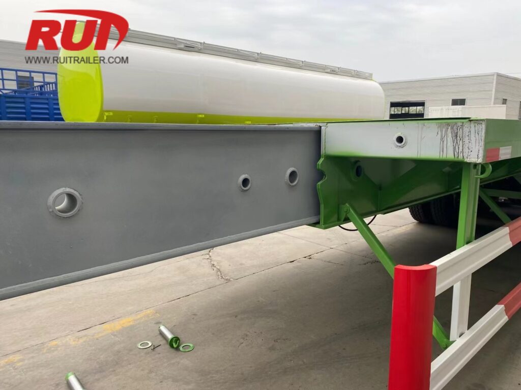
Ağırlık taşıma kapasitesi yüksek germe römorklarını, tam yük alanı izlerine, devlet köprü yasalarına ve aşırı yük gereksinimlerine uygun şekilde tasarlıyor ve üretiyoruz. Standart hazır spesifikasyonlar operasyonel sınırlarınızı karşılamadığında, mühendislik ekibimiz her boyutsal metriği sıfırdan uyarlamaktadır.
Yüksek Çekme Dayanımlı Çelik Çerçeve İmalatı
Taşıma kapasitesini maksimize etmek ve boş ağırlığı minimize etmek için, uzatılabilir römork şasisini yüksek verimli yapısal çelikler kullanarak inşa ediyoruz:
Q690 & HG785 Çelik: Orta açıklık kirişleri ve teleskopik iç tüpler üzerinde uygulanan yüksek mukavemetli yapısal dereceler, uzatıldığında orta açıklıkta sarkmayı önler.
Strenx 700 / Weldox: Aşırı yorgunluk direnci için yüksek stresli flanş bölümleri ve boğaz geçişlerinde kullanılan ultra yüksek verimli çelik plakalar.
Optimize Edilmiş Eğilme Kontrolü: Tamamen seviyeli kalmasını sağlamak için gövdeye doğrudan entegre edilmiş önceden eğimli tasarım ile tasarlanmış gövdeye yerleştirilmiş yapı.
Özel Hidrolik Uzatma Hareketleri ve Otomatik Menteşe Kontrolleri
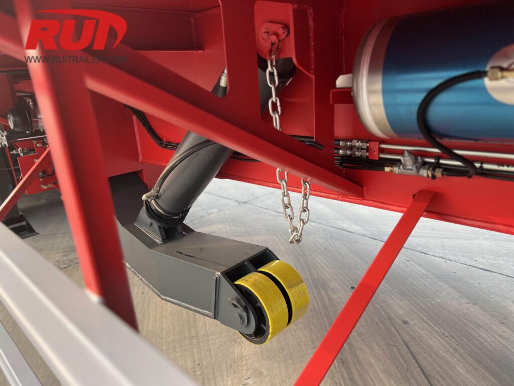
Filonuzun özel operasyonel iş akışlarına uygun uzatma mekanizmalarını tasarlıyoruz:
Özel Strok Uzunlukları: Hedeflenen açık ve kapalı uzunluklara ulaşmak için tasarlanmış tekli, ikili, üçlü veya dört kademeli teleskopik uzatmalar.
Hidrolik Sürgü Tahriği: Çift hidrolik silindir, traktörün çekme manevralarına gerek kalmadan şasiyi sorunsuz bir şekilde uzatmak veya toplamak için sürekli, kontrollü itme-çekme gücü sağlar.
Otomatik Havalı Kilitleme Pimleri: Kabin kontrollü ve treyler montajlı pnömatik kilit kontrolleri, 2 ft (600 mm) veya 5 ft (1.500 mm) aralıklarla güçlendirilmiş pim yataklarına kilitlenir.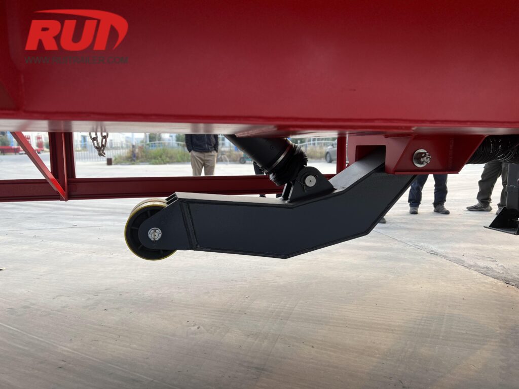
Aşırı Aks Yükleri için Modüler Entegrasyon
Katı köprü yasalarına uyum gerektiren mega yükler için, uzatılabilir şasilerimizi hızlı modüler bileşen entegrasyonu sağlayacak şekilde tasarlıyoruz:
Jeep Dolly Bağlantısı: Güçlendirilmiş ön pim yuvaları ve boyun (gooseneck) uzatmaları, dingil pimi ağırlığını ek ön aks hatlarına dağıtır.
Flip Akslar ve Azot Takviyeleri: Arka geçme (pin-on) flip akslar ve hidrolik/azot yük dengeleyici takviyeler, toplam dingil mesafenizi uzatır ve aks gruplarını aşırı yüklenmeye karşı korur.
Modüler Çoklu Aks Uyumluluğu: Ağır hizmet tipi modüler treyler tipleri ve teknik özellikleri ile tam uyumludur ve karmaşık çok akslı ağır nakliye taşımacılığı için özel sökülebilir boyunlu (RGN) treyler özelliklerine sahiptir.
Uzatılabilir Treyler Boyutları Hakkında Sıkça Sorulan Sorular
Çekilebilir römork için maksimum yasal uzatma uzunluğu nedir?
Kapandığında, standart birimler yasal boyutlarda çalışır 48 ft (14.63 m) or 53 ft (16.15 m) ile birlikte 8.5 ft (2.59 m) genişlik, izin gerektirmeden seyahat etmeye olanak tanır. Genişletildiğinde, tek aşamalı ve çok aşamalı uzatılabilir römork tasarımlar 80 ft (24.38 m) herhangi bir yerden ulaşır veya. 230+ ft (70+ m).
kadar uzayabilir. Bu genişletilmiş uzunluklarda çalışma, aşırı boyutlu yük düzenlemelerine tabidir ve eyalet veya bölgesel taşıma izinleri, belirlenmiş güzergah incelemeleri ve toplam kombinasyon uzunluğuna göre belirlenmiş eskort konfigürasyonları gerektirir.
Bir römorkun uzatılması, yoğun yük kapasitesini nasıl etkiler?
Şasi uzunluğu, römorkun yapısal eğilme momentini değiştirir. Kral başlığı ile arka aks grubu arasındaki açıklık arttıkça, izin verilen orta açıklıkta yoğun kapasite azalır: Tam Geri Çekili:.
Römork, maksimum derecelendirilmiş yükünü kısa bir platform bölgesi üzerinde yoğunlaştırır (genellikle 10 ila 15 ft / 3 ila 4.5 m). Tam Genişletilmiş: Maksimum yoğunlaştırılmış kapasite 40% ile 60%.
arasında düşer,
eğer yük kendinden destekliyse (örneğin çelik köprü kirişleri veya prefabrik beton gibi) veya ağırlık tüm omurga boyunca eşit dağılıyorsa.
Uzatılabilir Basamaklı Sal Dorse: arasında yüklenmiş güverte yükseklikleri sunar 34 inç ve 40 inç (864 mm ile 1.016 mm), uzun güverte kapasitesini alçak profilli geçiş mesafesiyle dengeler.
Uzatılabilir Lowboy / RGN: şu yükseklikten başlayan ultra alçak yüklenmiş güverte yükseklikleri sağlar 18 inç ila 24 inç (457 mm ila 610 mm) gerektirir 6 inç ila 8 inç (152 mm ila 203 mm) yerden yükseklik. Bir sökülebilir boyunlu uzatılabilir treyler uzun endüstriyel tekneleri, ağır tankları ve büyük boyutlu makineleri taşımak için standart seçimdir.
Uzatmalı bir treylerde ne zaman hidrolik zorlamalı direksiyon gereklidir?
Hidrolik zorlamalı direksiyon aksları, uzatılmış bir treylerin toplam uzunluğu aştığında gerekli hale gelir 80 ft ile 100 ft (24.38 m ile 30.48 m). Dingil mesafesi uzadıkça:
Standart sabit veya sürtünme-direksiyon akslar şiddetli lastik sürtünmesine ve yapısal yanal gerilmelere neden olur.
Hidrolik direksiyon bağlantıları veya otomatik döner tablolar şunları sağlar: 55 derecelik dönüş açıları, dönüş yarıçapını önemli ölçüde azaltır ve dar kavşaklarda yasal izin gereksinimleri içinde tarama yolunun boyutlarını korur.
Genişletilebilir bir römork, ara bloklama olmadan merkezi açıklıkta yoğun yükleri destekleyebilir mi?
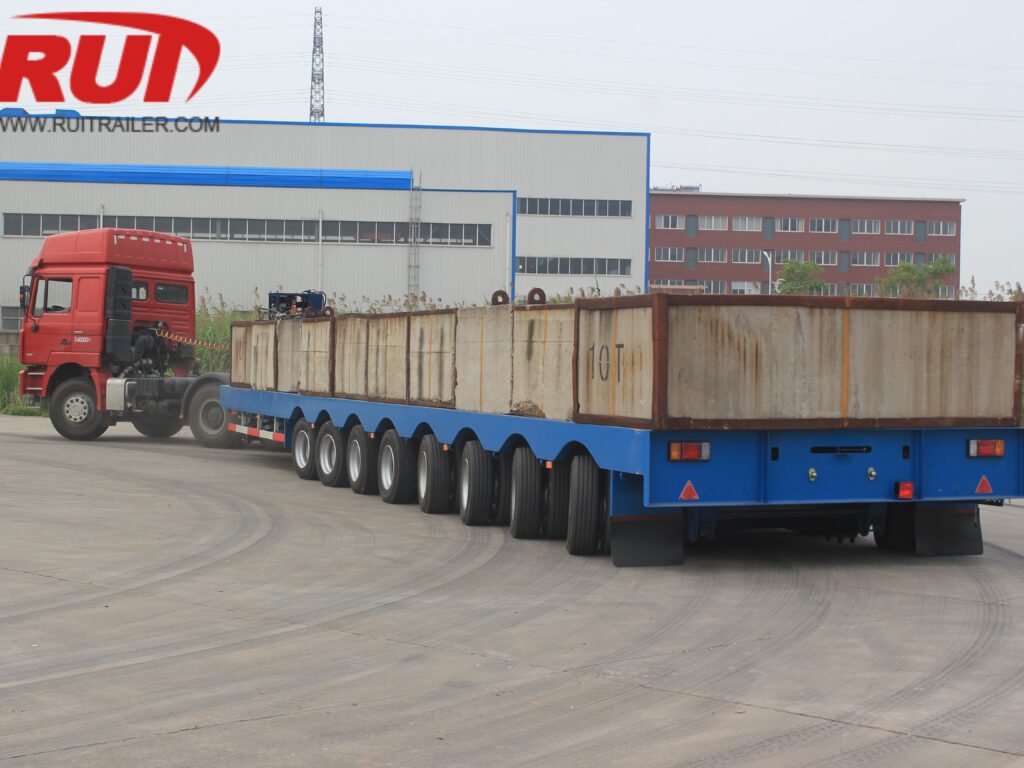
Hayır. Uzatılmış teleskopik kirişin desteklenmeyen orta bölümüne ağır makineleri nokta yüklemek kalıcı şasi eğilmesine veya yapısal arızaya neden olabilir. Kendinden destekli olmayan yoğun yükleri taşırken:
Yükü ana destek alanlarının üzerine yerleştirin (kuyruk geçişi veya arka tekerlek takımı üzerinde).
Yükleri doğrudan dış kutu kirişlerine aktarmak için ara çapraz destekler, yapısal takviye römorkları veya dağıtılmış blokaj kullanın.
 Turkish
  English
  German
  French
  Portuguese
  Russian
  Arabic
  Hindi
Hindi  Vietnamese
  Chinese
  Spanish
  Indonesian
  Swahili