

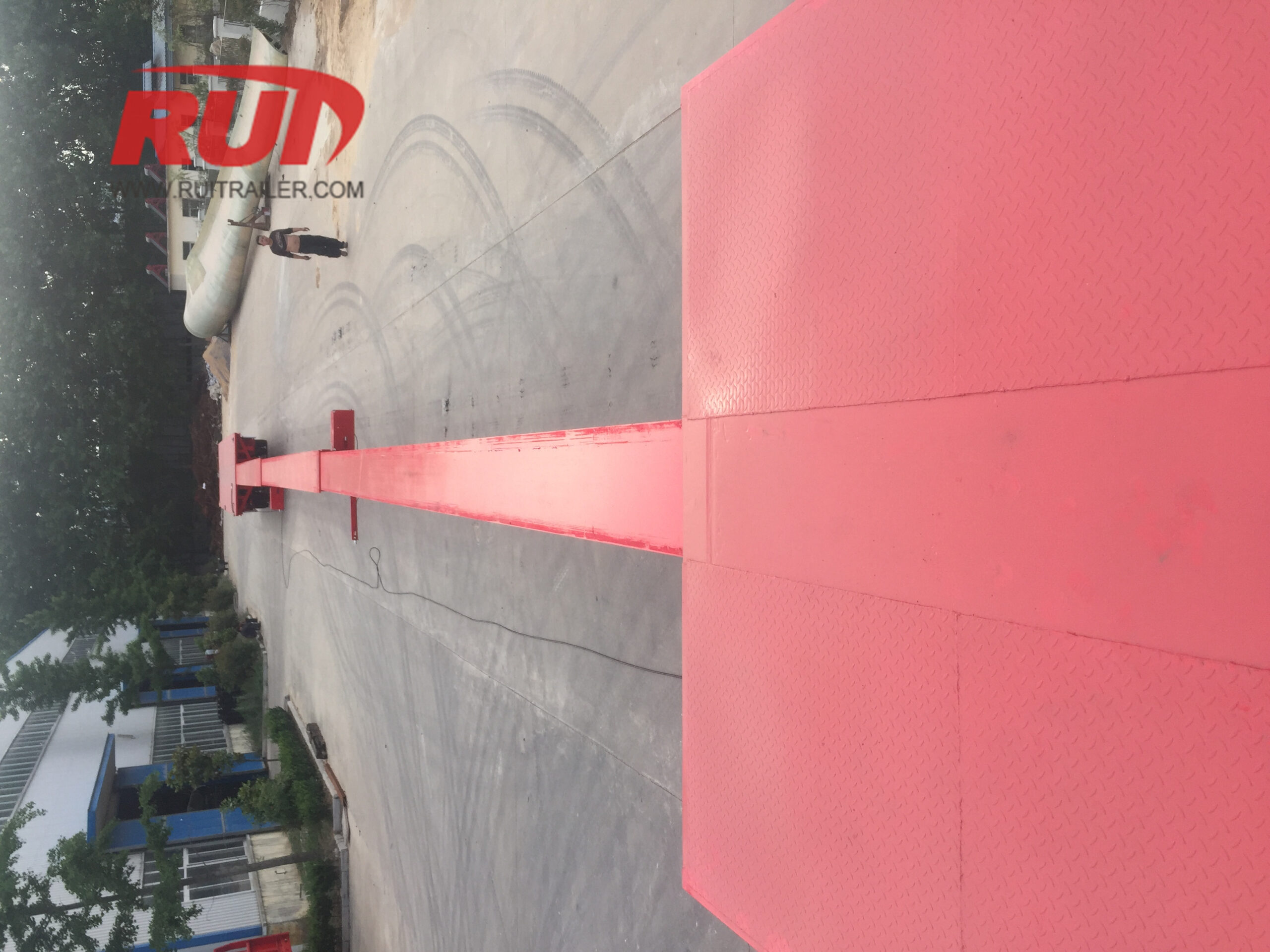
Standard-Erweiterbare Anhängermaße Referenzmatrix
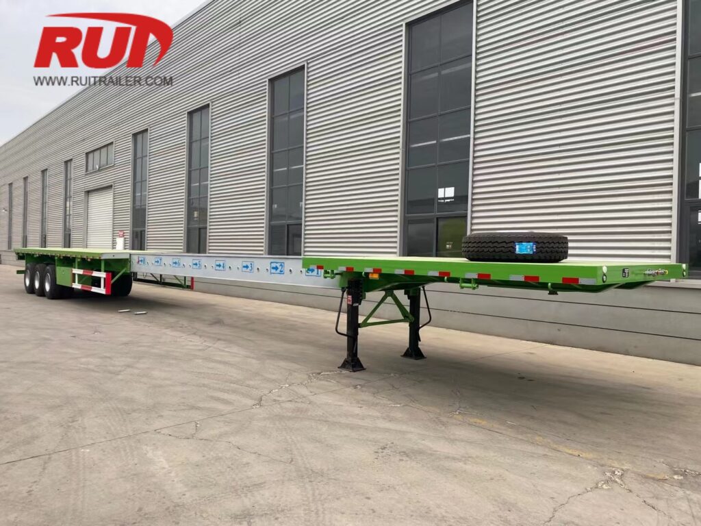
Die Zuordnung von extrem-langen Frachtstücken zu den richtigen erweiterbaren Anhängermaßen erfordert eine präzise dimensionale Planung. Beim Verlängern der Chassis-Länge müssen Frachtbetreiber Deckfreiheit, Achsabstand nach Brückenrecht und Biegemomente ausbalancieren. Wir entwickeln unsere teleskopischen Chassis so, dass sie in allen Erweiterungsstufen hohe Torsionsfestigkeit bewahren und gleichzeitig das Leergewicht optimieren.
Nachstehend befindet sich unsere Kern-Engineering-Referenzmatrix, die Standard-geschlossene Grundrisse mit maximalen Betriebsverlängerungen verschiedener Schwerlastanhänger vergleicht.
Engineering-Größenmatrix: Abmessungen, Freiräume und Kapazitäten
| Anhänger-Konfiguration | Eingezogene Länge | Maximale erweiterte Länge | Verwendbare Deckbreite | Ladekantenhöhe | Achskonfigurationen | Nennbare Nutzlastkapazität |
|---|---|---|---|---|---|---|
| Erweiterbarer Flachbettanhänger (Ein-Stufen) | 14,63 m / 48 ft | 24,38 m / 80 ft | 2.590 mm / 102 Zoll | 1.500 mm / 59 Zoll | 2 bis 3 Achsen | 40 Tonnen / 88.000 lbs |
| Ausziehbare Flachbett (Doppelstufe) | 16,15 m / 53 Fuß | 36,58 m / 120 Fuß | 2.590 mm / 102 Zoll | 1.500 mm / 59 Zoll | 3 bis 4 Achsen | 50 Tonnen / 110.000 lbs |
| Ausziehbare Stufendeck | 14,63 m / 48 ft | 22,86 m / 75 Fuß | 2.590 mm / 102 Zoll | 915 mm / 36 Zoll | 2 bis 4 Achsen | 43 Tonnen / 95.000 lbs |
| Ausziehbarer Lowboy (RGN-Well) | 7,92 m / 26 Fuß (Well) | 15,24 m / 50 Fuß (Well) | 2.590–3.048 mm / 102–120 Zoll | 457–610 mm / 18–24 Zoll | 3 bis 3+2 Achsen | 27.220 kg / 60 Tonnen |
| Mehrstufiger Teleskopklingenanhänger | 65 ft / 19,81 m | 230+ ft / 70,10 m | 100–118 Zoll / 2.540–3.000 mm | 38–48 Zoll / 965–1.220 mm | 3 bis 6 Achsen (lenkbar) | 120.000 Pfund / 55 Tonnen |
Kernmaßstäbliche Benchmarks
- Geschlossen vs. Verlängerte Länge: Standardrahmen beginnen bei den gesetzlichen Autobahnlängen (48 ft oder 53 ft) und verlängern sich durch innere Schiebebalken in kalibrierten Schritten von 2 ft bis 5 ft (600 mm bis 1.500 mm).
- Plattformhöhenprofile: Ausziehbare Lowboys bieten ultra-niedrige Ladeplattformhöhen bis zu 18 Zoll (457 mm), um hohe Industriekomponenten unter Überkopfkonstruktionen zu passen, während Stretch-Step-Decks durchschnittlich 36 Zoll (915 mm) für lange, mittelhohe Maschinen aufweisen.
- Achskonfiguration & Nutzlastmechanik: Wenn sich der Radstand vergrößert, nimmt die konzentrierte Tragfähigkeit in der Mittelöffnung ab. Wir integrieren hydraulische Selbstverfolgungs- oder Zwangslenkachsenlinien auf Plattformen, die über 24,38 m (80 Fuß) hinausgehen, um die Brückenformel einzuhalten und Reifenverschleiß bei engen Kurven zu reduzieren.
Erweiterbare Flachbettanhänger Maße (Trombone-Anhänger)
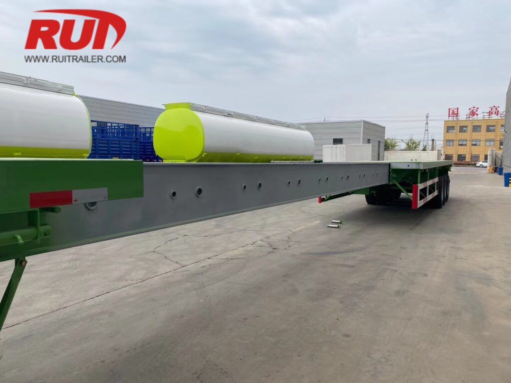
Wir entwickeln unsere Trombone- und Stretch-Flachbettanhänger, um Tragkonstruktionen aus Stahl, lange Rohre, Bewehrungsstahlbündel und selbsttragende Langladung zu transportieren, während sie gleichzeitig wendig genug bleiben, um leer unter Standard-legalen Abmessungen zu fahren.
Standardgröße des eingezogenen Chassis
Wenn geschlossen, entsprechen unsere Stretch-Flachbetten den Standardstraßenkonfigurationen, um ohne Übergrößenzulassung auf Rückfahrten zu fahren:
Basis 48-Fuß-Modell: Eingezogene Länge von 14,63 m (48 Fuß) mit einer Standarddeckbreite von 2,59 m (102 Zoll).
Basis 53-Fuß-Modell: Eingezogene Länge von 16,15 m (53 Fuß) mit einer Standarddeckbreite von 2,59 m (102 Zoll).
Verwendbare Deckbreite: 2,59 m (8 Fuß 6 Zoll) mit seitlichen Pfostenfächern, Schutzleisten und integrierten Rohrfächern.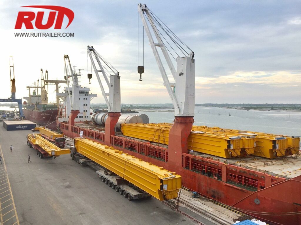
Ein- und Zweistufige Erweiterungsbereiche
Um extreme Längen zu ermöglichen, verwenden wir hochfeste Stahl-Teleskop-Boxträger, die reibungslos entlang Verschleißpolstern gleiten:
Ein-Stufen-Teleskopverlängerungen: Verlängert einen 14,63 m (48 Fuß) langen Anhänger auf bis zu 24,38 m (80 Fuß) oder einen 16,15 m (53 Fuß) langen Anhänger auf bis zu 27,43 m (90 Fuß).
Zweistufige Teleskopverlängerungen: Verwendet ein duales Schiebesystem mit zentralem Boxträger, das den Rahmen von 16,15 m (53 Fuß) auf insgesamt 36,58 m (120 Fuß) streckt.
Für betriebliche Parameter bei verschiedenen Langladungstransporten, siehe unseren erweiterbaren Anhänger vielseitiger Ladungskapazitätsleitfaden Bewertung der Rahmenbewertungen über verschiedene Spannen hinweg.
| Kennzahl | 48 ft Ein-Stufen | 53 ft Ein-Stufen | 53 ft Doppel-Stufen |
|---|---|---|---|
| Geschlossene Länge | 48 ft (14,63 m) | 53 ft (16,15 m) | 53 ft (16,15 m) |
| Maximale erweiterte Länge | 80 ft (24,38 m) | 90 ft (27,43 m) | 120 ft (36,58 m) |
| Deckbreite | 102 Zoll (2,59 m) | 102 Zoll (2,59 m) | 102 Zoll (2,59 m) |
| Ladekantenhöhe | 59 Zoll (1.498 mm) | 60 Zoll (1.524 mm) | 61 Zoll (1.549 mm) |
| Stiftverriegelungsintervalle | 2 ft / 5 ft (0,6 m / 1,5 m) | 2 ft / 5 ft (0,6 m / 1,5 m) | 2 ft / 5 ft (0,6 m / 1,5 m) |
Profilhöhen auf der Oberdeck auf 22,5-Zoll-Reifen
Beim Betrieb mit Standard-295/75R22,5 oder 11R22,5 Schwerlast-Reifen sind unsere ausziehbaren Flachbett-Deckhöhen für den direkten Einsatz von Gabelstaplern und Kränen optimiert:
Leerer Deckhöhenwert: 61 Zoll bis 63 Zoll (1.549 mm bis 1.600 mm) am Hinterachssystem.
Geladene Deckhöhe: Einstellen zwischen 59 Zoll und 60 Zoll (1.498 mm bis 1.524 mm) bei standardmäßiger gesetzlicher Achslast.
Unterrahmenfreiheit: 14 Zoll bis 18 Zoll (355 mm bis 457 mm) unter dem teleskopischen Mittenträger in der Mitte des Spannbereichs.
Pneumatische Verriegelungsstiftintervalle und Positionierung
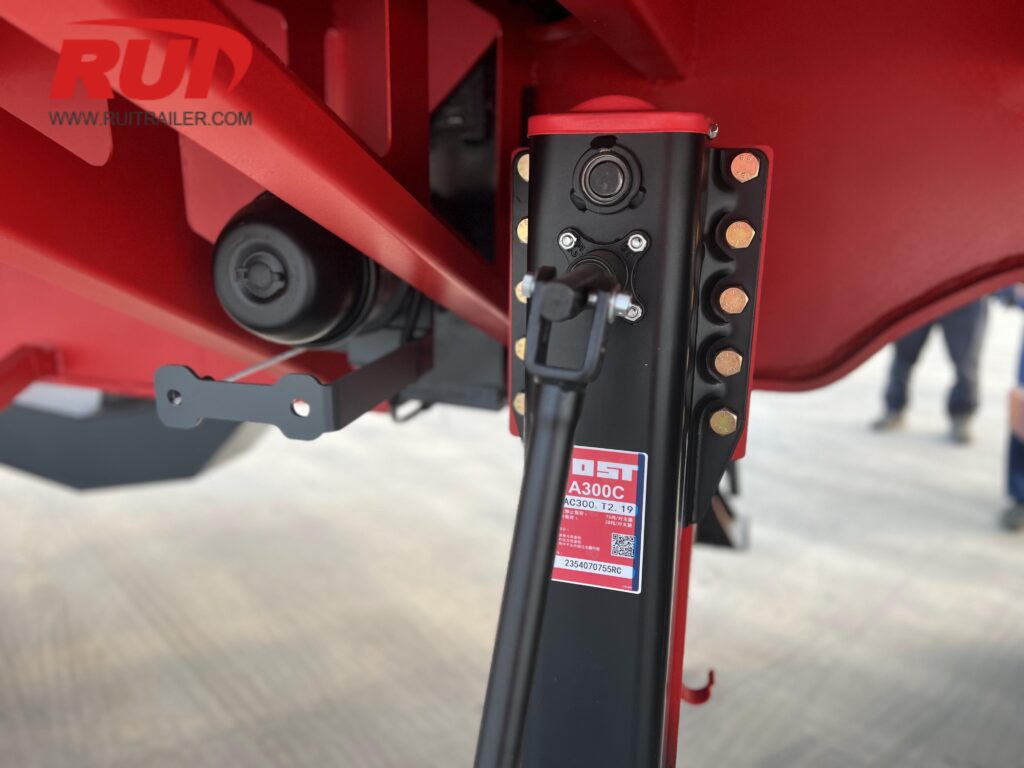
Unsere teleskopischen Fahrgestellsysteme verfügen über robuste pneumatische Verriegelungsstifte, die direkt vom Ventilkonsole des Fahrers oder über pneumatische Schalter im Fahrerhaus gesteuert werden:
Verriegelungsintervalle: Präzise gebohrte Stoppstellen für Stifte, positioniert alle 24 Zoll (610 mm) oder 60 Zoll (1.524 mm) entlang des Hauptstrukturbalkens.
Kabelschächte mit Energiekette: Vollständig geschlossene Energieketten schützen Luftbremsleitungen und elektrische Kabelbäume vor Einklemmen, Verhaken oder Dehnung, wenn das Fahrgestell geöffnet und geschlossen wird.
Luftbetätigte Freigabe: Federbelastete Sicherheitsriegel sorgen dafür, dass die Stifte auch bei Druckverlust während des Transports mechanisch verriegelt bleiben.
Erweiterbare Stufenbett- und Drop Deck-Größen
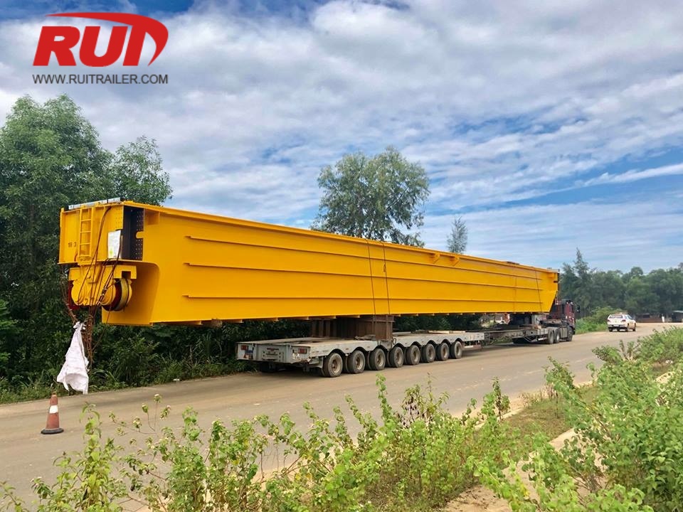
Unsere erweiterbaren Stufenbett- (Drop Deck) Anhänger lösen die Herausforderung, lange Ladung zu transportieren, die für ein Standard-Flachbett zu hoch ist. Durch die Senkung des Schwerpunkts und die Bereitstellung variabler Decklängen ermöglichen diese Anhänger den Transport von hohen, selbsttragenden Industrie-Frachten, während sie innerhalb der Standard-Brückenfreiheit bleiben.
Oberdecklänge vs. Erweiterbare Unterdeckmaße
Das Fahrgestell-Layout teilt den nutzbaren Deckraum in ein festes Oberdeck und einen teleskopischen unteren Wellbereich:
- Oberdeck (Gooseneck-Bereich): Misst typischerweise 3,048 mm bis 3,353 mm (10 ft bis 11 ft) in der Länge und bietet eine standardmäßige 1.524 mm (60 Zoll) hohe Beladungshöhe für Unterstützungsausrüstung, Rigging oder kleinere sekundäre Ladung.
- Geschlossener Unterraum: Bietet eine Grundlänge des freien Decks von 11.278 mm bis 12.800 mm (37 ft bis 42 ft).
- Erweiterter Unterraum: Ein-Stufen-Teleskopmittenbalken erweitern das Hauptdeck auf 19.200 mm bis 22.860 mm (63 ft–75 ft), was zu einer Gesamtlänge des erweiterten Anhängers von bis zu 26.212 mm (86 ft) führt.
+------------------+----------------------------------------------------+
| Feste Oberdeck | Erweiterbarer Unterraum (Hauptdeck) |
| 10 ft - 11 ft | Geschlossen: 37 ft - 42 ft ===> Erweiterbar: Bis zu 75 ft |
+------------------+----------------------------------------------------+
Niedrigprofil-Deckhöhen für hohen Frachtraum
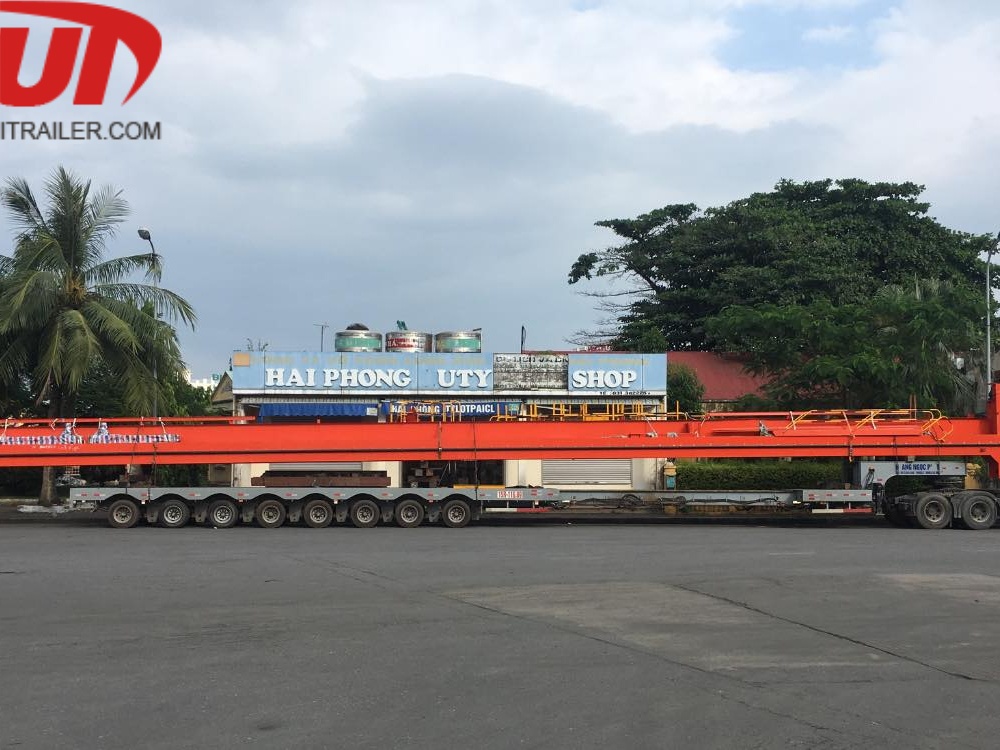
Die niedrige Deckhöhe ermöglicht die gesetzliche Überkopf-Freigabe für hohe Maschinen, Schiffe und Strukturelemente. Unsere standardmäßigen erweiterbaren Drop-Deck-Anhänger bieten eine beladene Unterdeckhöhe zwischen 864 mm und 1.016 mm (34 in bis 40 in) bei 255/70R22.5 Niedrigprofilreifen.
Wenn extreme vertikale Freigaben erforderlich sind, entwickeln wir super-niedrige Konfigurationen mit 17,5-Zoll-Fahrwerk, um die beladene Deckhöhe auf 762 mm bis 838 mm (30 in bis 33 in) zu senken. Für extreme Anwendungen, die noch niedrigere Bodenprofile erfordern, fertigen wir auch spezielle Ausrüstungen wie unseren Niedrigprofil-Deck-Modulanhänger der für strenge Überkopf-Beschränkungen ausgelegt ist.
Erweiterbare Drop-Deck-Dimensionale Spezifikationen
| Spezifikation Metrisch | Standard Imperial | Standard Metrisch |
|---|---|---|
| Gesamtlänge (geschlossen) | 48 ft / 53 ft | 14.630 mm / 16.154 mm |
| Gesamtlänge (voll ausgefahren) | 75 ft bis 86 ft | 22.860 mm bis 26.212 mm |
| Hauptwannenlänge (ausgefahren) | Bis zu 75 ft | Bis zu 22.860 mm |
| Geladene Wannenhöhe | 34 Zoll bis 40 Zoll | 864 mm bis 1.016 mm |
| Standard-Deckbreite | 8 ft 6 in (102 in) | 2.590 mm |
| Ausleger-Erweiterte Breite | Bis zu 3,20 m | Bis zu 3.200 mm |
| Bodenfreiheit (beladen) | 8 Zoll bis 10 Zoll | 203 mm bis 254 mm |
Drop-Transition- und Biber-Schwanz-Freigaben
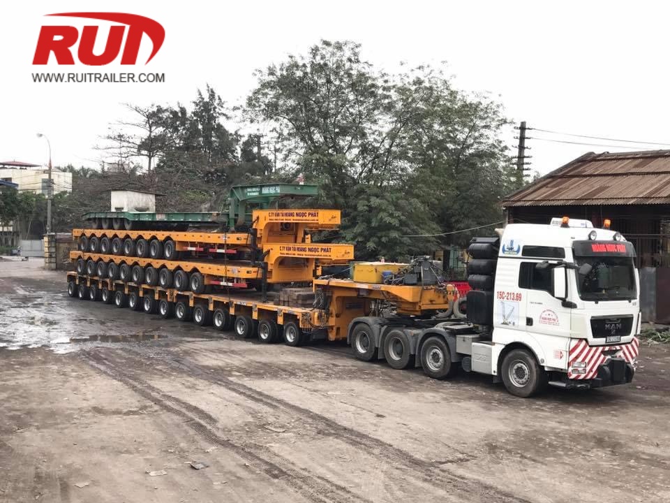
- Drop-Transition-Neigung: Mit einer sauberen 45- oder 90-Grad-Übergang vom Oberdeck zum Unterdeck gebaut. Dieses Design verhindert, dass lange Strukturlasten beim Transport hochzentrieren.
- Hintere Achswechsel: Ein konischer Übergang zum hinteren Fahrwerk stellt sicher, dass lange Geräte, die die Mulde passieren, nicht am Hinterachsenrahmen hängen bleiben.
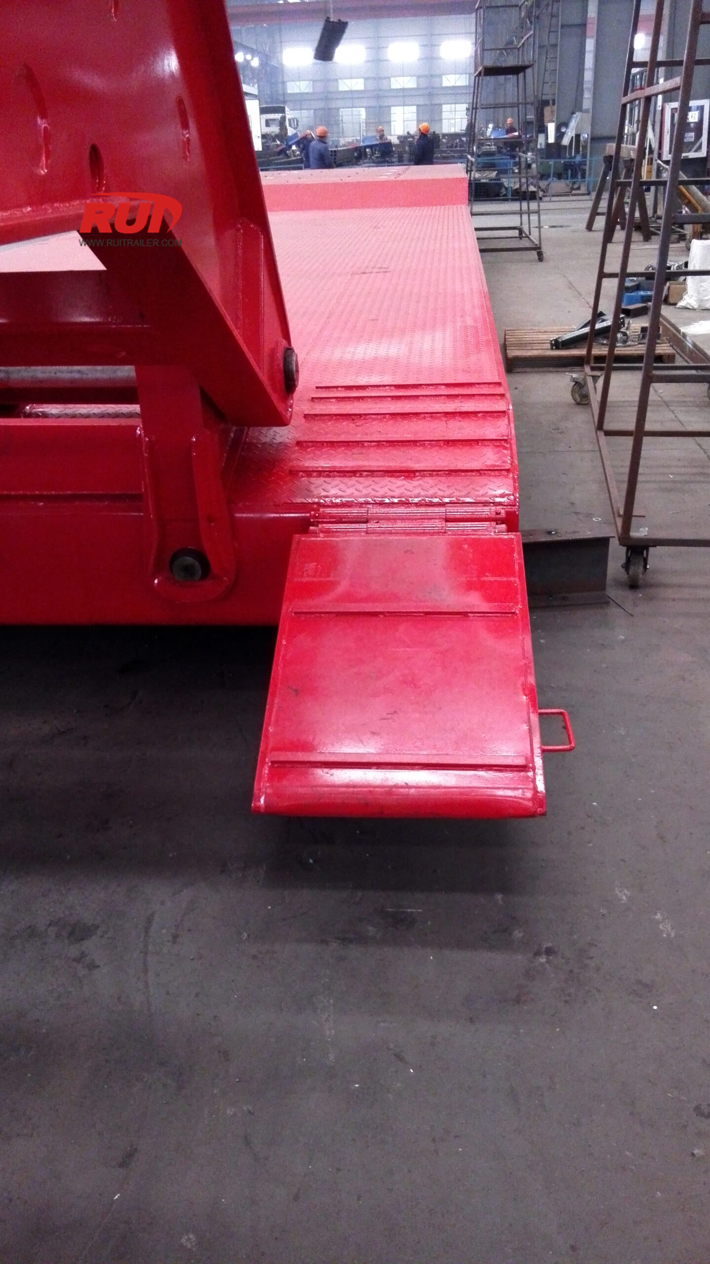
- Biber-Schwanz- und Rampe-Optionen: Optionale 1,20 m bis 1,52 m lange Biber-Schwänze mit robusten, federgestützten oder hydraulischen Rampen bieten einen Ladewinkel von 14 bis 16 Grad für fahrbare Geräte.
Extendable Lowboy and RGN Trailer Dimensions
When moving tall, self-supporting cargo like industrial autoclaves, refinery components, or heavy machinery, combining low deck heights with adjustable length is essential. Our stretch lowbed and detachable gooseneck platforms solve tight vertical clearances while accommodating elongated wheelbases. To explore standard platform setups, review our comprehensive lowboy trailer guide to types, specs, and uses.
Clear Well Deck Lengths from 26 ft Closed up to 65 ft Extended
The clear loading well provides the primary platform for concentrated heavy freight. Our extendable lowboy dimensions deliver the following standard length stages:
- Retracted Base Well: 26 ft to 30 ft (7.92 m to 9.14 m) for standard regional travel and empty deadheading.
- Fully Extended Span: 50 ft to 65 ft (15.24 m to 19.81 m) of clear well deck space for long-span structures.
- Total Overall Length: Extends from 53 ft (16.15 m) closed up to 90+ ft (27.43+ m) including gooseneck and rear tandem/tridem bogie assemblies.
Ultra-Low Loaded Ground Clearance Profiles (18 in to 24 in)
Minimizing top-of-deck elevation allows extra room under highway bridges and power lines:
- Geladene Deckhöhe: 18 in to 24 in (457 mm to 610 mm) under full payload weight.
- Loaded Ground Clearance: 4 in to 6 in (102 mm to 152 mm) running clearance, designed to prevent bottoming out across railroad crossings and uneven intersections.
- Deck Design Variants: Flat well, drop-side beam, or beam-and-stirrup configurations for ultra-tall freight cradling.
Main Beam Slide Inserts and Hydraulic Pin Interlocks
Telescoping under heavy loads requires robust structural locking mechanics. We build these stretch wells with high-strength telescoping structural box girders and precise locking systems:
| Dimensional Parameter | Imperial Spec | Metric Spec |
|---|---|---|
| Retracted Well Length | 26 ft – 30 ft | 7.92 m – 9.14 m |
| Max Extended Well Length | 50 ft – 65 ft | 15.24 m – 19.81 m |
| Loaded Well Deck Height | 18 in – 24 in | 457 mm – 610 mm |
| Ground Clearance (Laden) | 4 in – 6 in | 102 mm – 152 mm |
| Locking Pin Intervals | Every 24 in to 60 in | Every 600 mm to 1,500 mm |
- High-Yield Inner and Outer Beams: Fabricated from heavy-tensile steel to resist deflection over long spans without adding deadweight.
- Air and Hydraulic Pin Stops: High-shear lock pins engage securely at defined increments along the extension spine.
- Smooth Detachable Transitions: Seamless connection to our front neck designs, matching the operational flexibility found across our RGN removable gooseneck trailer line.
Multi-Stage Telescopic Blade Trailer Dimensions
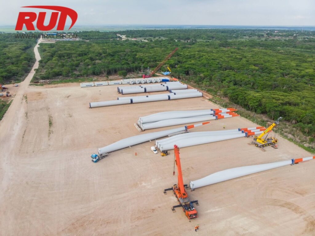
Transporting modern onshore wind turbine blades requires extreme reach and torsional stability. We design our multi-stage telescopic blade trailers to handle massive blade lengths while maintaining strict roadway compliance during unladen return trips.
Multi-Stage Telescopic Extension Dynamics
Our multi-stage telescopic trailer chassis utilize 3-stage, 4-stage, and 5-stage extension beams that adjust dynamically based on blade length:
- Closed Length: 65 ft to 72 ft (19.8 m to 21.9 m) for legal empty transit.
- Maximum Extended Length: Expands seamlessly from 175 ft up to 230+ ft (53.3 m to over 70 m).
- Intermediate Locking Steps: Automatic pneumatic locking pins secure the telescopic sections at custom intervals every 3 ft to 5 ft (0.9 m to 1.5 m).
- Rear Bogie Configuration: 3 to 6 hydraulic pendular axle lines deliver a tight turning radius and auto-tracking steering.
For regional route configurations, deploying a dedicated Windturbinenblatt-Anhänger ensures your overall combination length stays within permitted lane paths while clearing roadway pinch points.
Torsional Box-Beam Profile
Extreme extension spans generate severe bending moments. We build the central spine using a high-strength, enclosed box-beam profile manufactured from high-yield structural steel:
- Chassis Resistance: The enclosed central spine prevents lateral deflection and eliminates torsional chassis twisting across spans exceeding 200 ft (61 m).
- Internal Cable/Hose Tracks: Energy chains run internally through the telescopic beams, shielding hydraulic lines and electrical wiring from binding or road debris during telescoping strokes.
| Specification Parameter | Standard Imperial | Standard Metrisch |
|---|---|---|
| Retracted Total Length | 65 ft 7 in | 20,000 mm |
| Fully Extended Total Length | 232 ft 11 in | 71,000 mm |
| Extension Stages | 3 to 5 Stage Telescopic | 3 to 5 Stage Telescopic |
| Loaded Deck Height (Rear Bogie) | 37 in to 41 in | 950 mm to 1,050 mm |
| Chassis Width | 8 ft 4 in to 9 ft 10 in | 2,550 mm to 3,000 mm |
Hydraulic Turntables and Blade Root Adapter Sizing
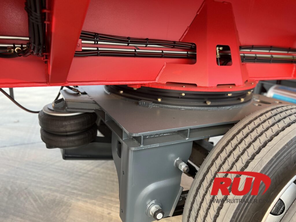
Securing root-end diameters requires rigid mounting interfaces to absorb acceleration and braking forces:
- Integrated Turntables: Hydraulic sliding bolsters absorb transport friction and compensate for blade flex over uneven terrain.
- Root Clamping Fixtures: Universal bolt-circle root adapters adjust to fit standard 9.8 ft to 14.8 ft (3.0 m to 4.5 m) blade root diameters.
- Extreme Terrain Maneuverability: For mountainous wind farm access roads, pairing the chassis with a specialized Rotorblattadapter allows up to 60-degree blade tilt angles and full 360-degree rotation to clear tree lines and tight hillside curves.
Width, Clearance, and Structural Deflection Parameters
Controlling overall width, tractor clearances, and mid-span chassis deflection is essential when configuring heavy-haul stretch equipment. As extendable trailer dimensions grow longer, managing structural geometry ensures the rig remains legally compliant, stable, and clear of the pavement under maximum payload.
Chassis Width Ratings and Swing-Out Outriggers
Standard extendable platforms feature a baseline transport width of 8 ft 6 in (2.59 m / 2,590 mm) to comply with non-permitted highway transit rules. For oversized cargo, heavy equipment, and wide machinery footprints, we integrate heavy-duty swing-out outriggers (side brackets) along the perimeter beams.
- Standard Base Width: 8 ft 6 in (2.59 m / 2,590 mm)
- Expanded Outrigger Width: 10 ft 0 in to 12 ft 0 in (3.05 m to 3.66 m / 3,050 mm to 3,660 mm)
- Outrigger Capacity: Rated to support distributed perimeter loads using heavy hardwood or aluminum outrigger planks.
| Specification Parameter | Standard Imperial | Metric (ISO) | Application / Function |
|---|---|---|---|
| Base Deck Width | 8 ft 6 in (102 in) | 2.590 mm | Standard legal travel lane width |
| Ausleger-Erweiterte Breite | 10 ft 0 in – 12 ft 0 in | 3,050 mm – 3,660 mm | Wide machinery and vessel support |
| Gooseneck Swing Radius | 84 in – 110 in | 2,134 mm – 2,794 mm | Cab and frame clearance for multi-axle tractors |
| Kingpin Setback Settings | 16 in, 24 in, 36 in | 406 mm, 610 mm, 914 mm | Optimizes tractor drive-axle weight distribution |
| Spine Pre-Camber Arch | 1.5 in – 3.5 in | 38 mm – 89 mm | Deflection counter-measure under loaded span |
Gooseneck Swing Radius, Kingpin Settings, and Tractor Clearances
Proper clearance between the tractor frame, cab sleeper, and trailer neck prevents contact during tight maneuvering. We engineer adjustable, multi-position commercial kingpins (2-inch / 50.8 mm and 3.5-inch / 88.9 mm options) to match diverse tractor wheelbases and rear drive axle groupings.
- Dual Kingpin Locations: Dual-setting baseplates allow fast adjustments between 16 in (406 mm) and 36 in (914 mm) setbacks.
- Gooseneck Clearance: Engineered swing profiles ranging from 84 in to 110 in (2,134 mm to 2,794 mm) accommodate 3-axle and 4-axle heavy-haul tractors, integrating smoothly with configurations like a Klappbarer Schwanenhals-LKW to clear rear winch frames and fenders.
Pre-Cambered Spine Engineering to Counter Mid-Span Sagging
When a telescopic beam extends to long spans, natural bending moments increase. Without proper design, this flex causes structural sagging in the middle of the trailer, dropping loaded deck ground clearance below safe margins and risking ground strikes over railroad crossings and road crowns.
- Built-In Upward Arch: We fabricate our main central spine with positive pre-camber (an upward arch of 1.5 in to 3.5 in / 38 mm to 89 mm when empty).
- Loaded Deflection Control: As the trailer carries concentrated freight at maximum extension, the engineered flex draws the deck down into a flat, level plane.
- High-Yield Steel Construction: Built with high-tensile steel box beams, the chassis resists permanent deformation and maintains full structural integrity across varied stretch lengths.
Axle Spacing, Steering Geometry, and Bridge Law Compliance
When expanding extendable trailer dimensions for extreme payloads, managing weight distribution and maneuverability becomes critical. Extending the wheelbase alters axle loading under the Federal Bridge Formula, requiring specific axle group spreads and active steering mechanisms to remain road-legal and maneuverable.
Bridge Formula Axle Grouping Configurations
Stretching a chassis shifts the inner bridge spacing, changing legal axle weight allowances across highway networks. We engineer our rear bogies with versatile spacing layouts:
Standard Tandem & Tridem Spreads: Fixed or sliding axle spacings set at 54 in (1,370 mm), 60 in (1,524 mm), or 72 in (1,829 mm) to optimize gross vehicle weight ratings (GVWR).
Wide-Spread & Quad Configurations: Spacings up to 108 in (2,743 mm) or modular 4-axle groupings to distribute concentrated weight evenly across road bridges.
Tare Weight Optimization: Precise kingpin-to-center-axle distance settings ensure compliance with regional bridge formulas without overloading tractor drive axles.
+------------------------------------------------------------------------------------+
| Retracted / Extended Wheelbase | Bridge Formula Compliance | Axle Group Load Split |
+------------------------------------------------------------------------------------+
| 48 ft (14.6 m) closed | Standard Legal Limits | Direct 50/50 Tandem |
| 80-120+ ft (24.4-36.5+ m) open | Permitted Oversize Bridge | Active Distributed |
+------------------------------------------------------------------------------------+
Hydraulic Forced-Steering Systems (Up to 55° Angle)
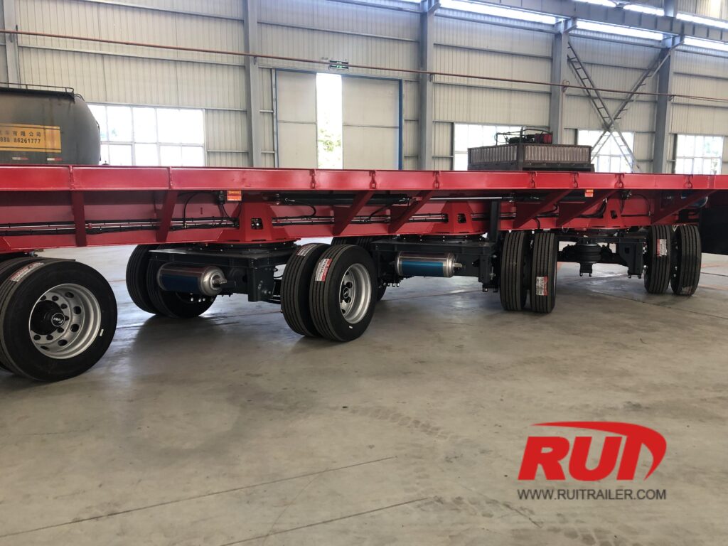
Long stretch trailer dimensions create severe tire scrubbing and tight cornering challenges on urban or mountain routes. We equip our multi-stage and heavy-haul trailers with high-angle steering integration:
Wedge & Turntable Control: Mechanical-hydraulic steering linkages synchronize the gooseneck kingpin pivot angle with the rear axle bogie.
Extreme Turning Radius: Hydraulic axles for heavy duty industrial applications deliver progressive steering angles up to 55 degrees, drastically cutting cut-in tracking.
Wireless Remote Override: Handheld wireless remote control allows operators to steer rear axles independently at low speeds to navigate complex roundabouts and tight job sites.
Lift Axle Deployment for Unladen Return Runs
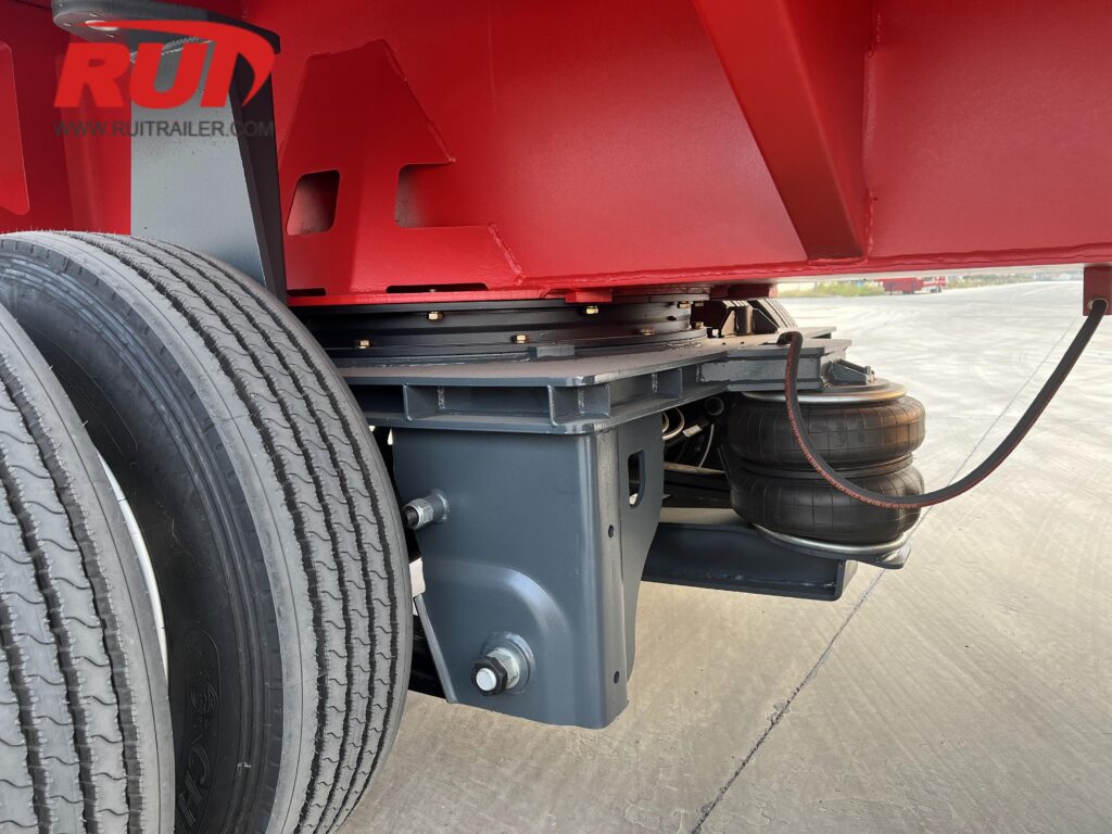
Dragging multi-axle assemblies on unloaded return trips drives up fuel consumption and tire wear.
Automated Pneumatic & Hydraulic Lifts: Raise front or rear auxiliary axles when running empty to shorten the ground-contact wheelbase.
Tire Scrub & Drag Reduction: Eliminates lateral tire drag on tight turns while empty, saving tire life and lowering toll category fees across transport routes.
Cargo Dimensional Matching and Load Sizing
Matching your payload's physical footprint to the correct extendable trailer dimensions prevents structural overloading, excessive deflection, and overhead clearance violations. We engineer our telescopic chassis around three distinct cargo categories:
Precast Concrete and Structural Steel Girders
Long structural spans are typically self-supporting along their length but demand precise support placement at designated bearing points:
Support Point Placement: We configure our telescopic chassis locking intervals to align bolster bunks directly under the girder's engineered pick points, preventing negative bending moments during transit.
Span vs. Rating: A standard 53 ft (16.15 m) stretch flatbed extended to 90 ft (27.43 m) shifts the structural workload to the central spine. For non-self-supporting steel members, mid-span blocking or twin-spine chassis designs are required to maintain legal deflection limits under 1.5 in (38 mm).
Wind Turbine Towers vs. Rotor Blades
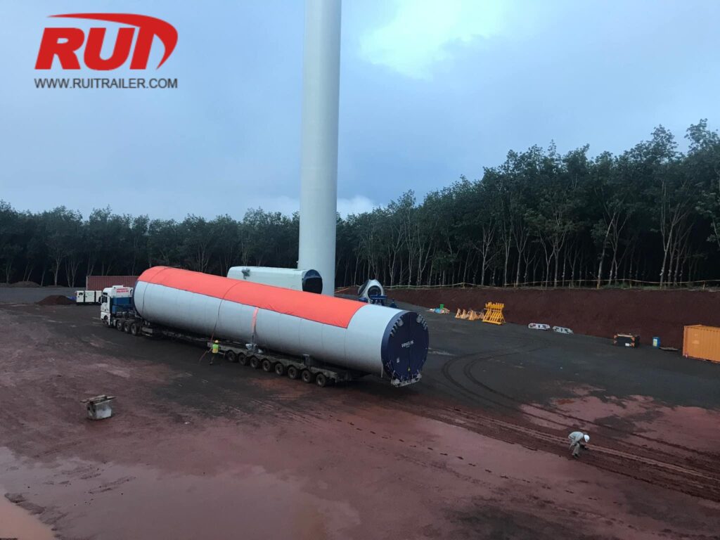
Wind energy components present completely different dimensional challenges:
Turmsegmente: Large-diameter base and mid sections require maximum concentrated weight capacity combined with an ultra-low loaded deck height (under 18 in / 457 mm) to clear highway overpasses. We utilize our heavy-duty front-loading low bed trailer for heavy haul configurations with extendable well decks to carry these heavy cylindrical loads safely.
Rotor Blades: Modern 70 m to 100+ m (230 ft to 330 ft) blades exert minimal axle weight but generate massive tail-swing and wind shear. We build 3-stage and 4-stage telescopic blade trailers extending up to 240 ft (73.15 m), integrated with turntable root adapters and forced-steering rear bogies to track safely through tight turns.
Overhead Clearance Sizing for Pressure Vessels
Industrial vessels, fractionators, and autoclaves require strict vertical dimension management:
Transit Height Calculation: Total transit height equals the vessel outer diameter plus cradle saddle height and loaded deck ground clearance.
Deck Optimization: To haul a 12 ft (3.66 m) diameter tank under a standard 14 ft 6 in (4.42 m) overhead bridge clearance, loaded deck height must not exceed 24 in (610 mm). For these extreme loads, we configure low-profile extendable well decks that drop to 12 in to 15 in (305 mm to 381 mm) of ground clearance under full load.
Custom Telescopic Trailer Engineering and Manufacturing Capabilities
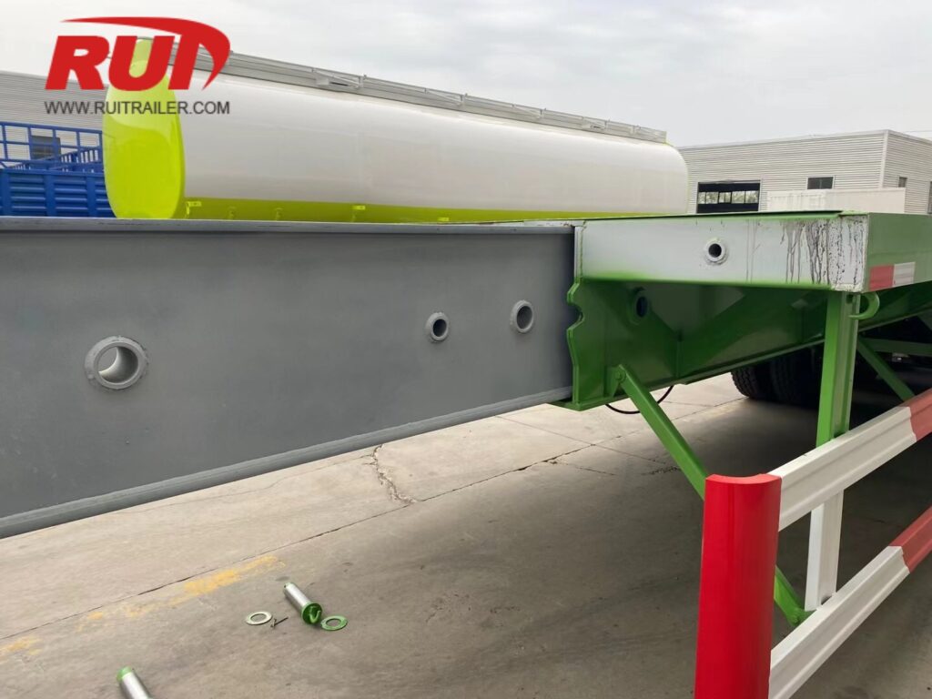
We design and manufacture heavy haul stretch trailers to match exact cargo footprints, state bridge laws, and extreme load requirements. When standard off-the-shelf specs do not meet your operational limits, our engineering team tailors every dimensional metric from the ground up.
High-Tensile Steel Frame Fabrication
To maximize payload while minimizing tare weight, we build our extendable trailer chassis using high-yield structural steels:
Q690 & HG785 Steel: High-strength structural grades applied to central box beams and telescopic inner tubes to prevent mid-span sagging when extended.
Strenx 700 / Weldox: Ultra-high-yield steel plates used in high-stress flange sections and gooseneck transitions for extreme fatigue resistance.
Optimized Deflection Control: Engineered pre-camber built directly into the spine to ensure the deck remains completely level under full concentrated load ratings.
Custom Hydraulic Extension Strokes and Automated Pin Controls
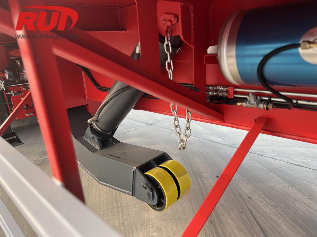
We engineer extension mechanisms around your fleet's specific operational workflows:
Custom Stroke Lengths: Single, double, triple, or four-stage telescopic extensions designed to achieve your target open and closed lengths.
Hydraulic Slide Actuation: Dual hydraulic cylinders provide continuous, controlled push-pull power to extend or retract the chassis smoothly without requiring tractor pulling maneuvers.
Automated Air-Release Lock Pins: Cab-controlled and trailer-mounted pneumatic locking controls lock into reinforced pin collars at 2 ft (600 mm) or 5 ft (1,500 mm) intervals.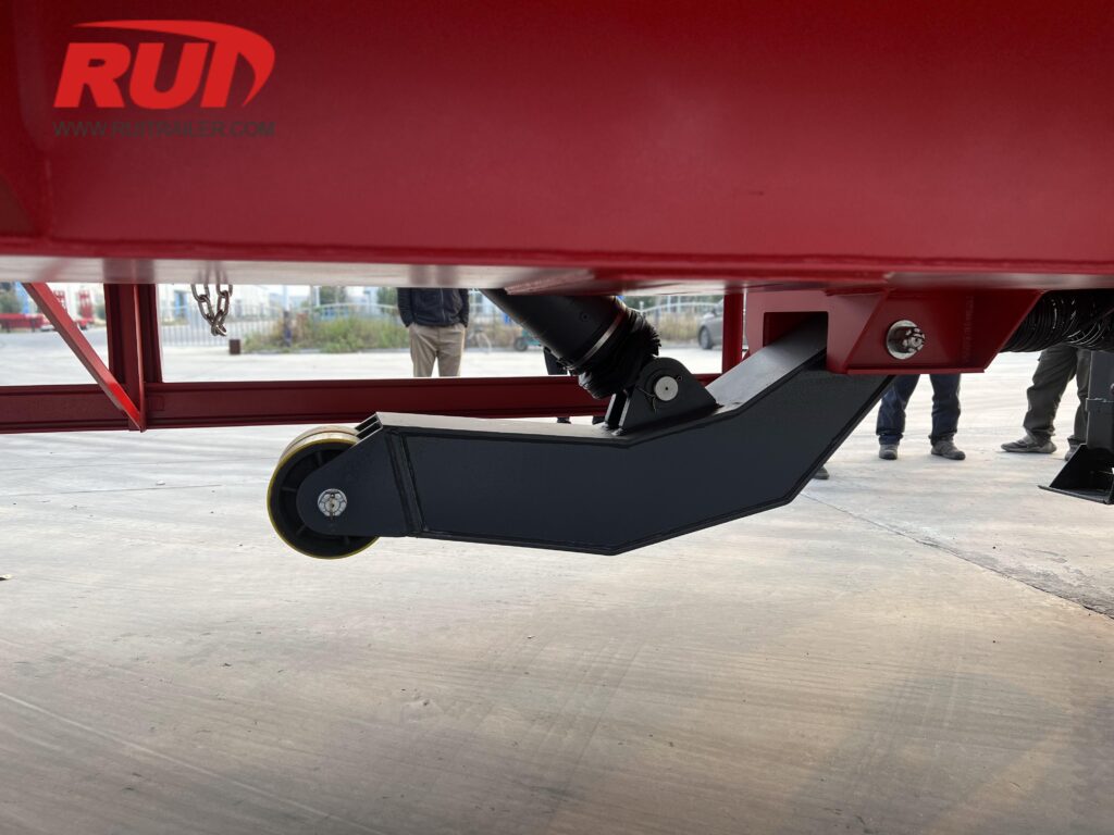
Modular Integration for Extreme Axle Loads
For mega-loads requiring strict bridge law compliance, we engineer our extendable chassis for rapid modular component integration:
Jeep Dolly Connectivity: Reinforced front pin boxes and gooseneck extensions distribute kingpin weight across additional forward axle lines.
Flip Axles & Nitrogen Boosters: Rear pin-on flip axles and hydraulic/nitrogen load-equalizing boosters extend your overall wheelbase and protect axle groups against overload.
Modular Multi-Axle Compatibility: Fully compatible with our heavy-duty modular trailer types and specs and specialized detachable gooseneck RGN trailer features for complex multi-axle heavy-haul transport.
Frequently Asked Questions About Extendable Trailer Dimensions
What is the maximum legal extension length for an extendable trailer?
When closed, standard units run at legal dimensions of 48 ft (14,63 m) or 53 ft (16,15 m) with an 8.5 ft (2.59 m) width, allowing permit-free travel. Once expanded, our single-stage and multi-stage erweiterbarer Anhänger designs reach anywhere from 80 ft (24,38 m) up to 230+ ft (70+ m). Operating at these extended lengths falls under oversize load regulations, requiring state or regional transport permits, designated route surveys, and specific escort configurations based on overall combination length.
How does extending a trailer affect its concentrated load capacity?
Lengthening the chassis alters the trailer's structural bending moment. As the span between the kingpin and rear axle group increases, allowable mid-span concentrated capacity decreases:
Fully Retracted: The trailer supports its maximum rated payload concentrated over a short deck section (typically 10 to 15 ft / 3 to 4.5 m).
Fully Extended: The maximum concentrated capacity drops by 40% to 60% unless the cargo is self-supporting (such as steel bridge girders or precast concrete) or the weight is uniformly distributed across the entire spine.
What deck height is best for over-height extendable freight?
Deck height selection depends directly on payload height and route overhead restrictions:
Extendable Step Deck: Offers loaded deck heights between 864 mm und 1.016 mm (34 in bis 40 in), balancing long deck capability with low-profile clearance.
Extendable Lowboy / RGN: Delivers ultra-low loaded deck heights from 18 in to 24 in (457 mm to 610 mm) mit 6 in to 8 in (152 mm to 203 mm) of ground clearance. A removable gooseneck extendable trailer is the standard choice for moving tall industrial vessels, heavy tanks, and oversized machinery.
When is hydraulic forced steering required on a stretch trailer?
Hydraulic forced-steering axles become necessary once an extended trailer's overall length exceeds 80 ft to 100 ft (24.38 m to 30.48 m). As the wheelbase stretches:
Standard fixed or friction-steer axles cause severe tire scrub and structural lateral stress.
Hydraulic steering linkages or automated turntables provide up to 55-degree turning angles, drastically reducing the turning radius and keeping swept-path dimensions within legal permit requirements on tight intersections.
Can an extendable trailer support concentrated loads in the center span without intermediate blocking?
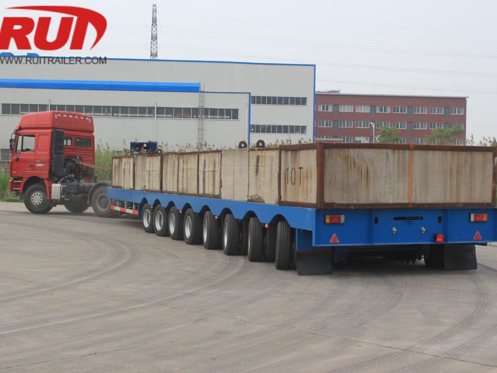
No. Point-loading heavy machinery in the unsupported center section of an extended telescopic beam can cause permanent chassis deflection or structural failure. When moving non-self-supporting concentrated cargo:
Position the payload over the main support areas (over the gooseneck transition or the rear bogie).
Use intermediate cross-bunk supports, structural bolster dollies, or distributed blocking to transfer load forces directly into the outer box beams.
 German
  English
  Turkish
  French
  Portuguese
  Russian
  Arabic
  Hindi
Hindi  Vietnamese
  Chinese
  Spanish
  Indonesian
  Swahili